In the previous posts of this series
- Fun with veth-devices, Linux bridges and VLANs in unnamed Linux network namespaces – I
- Fun with veth-devices, Linux bridges and VLANs in unnamed Linux network namespaces – II
- Fun with veth-devices, Linux bridges and VLANs in unnamed Linux network namespaces – III
- Fun with veth-devices, Linux bridges and VLANs in unnamed Linux network namespaces – IV
we laid the foundations for working with VLANs in virtual networks between different network namespaces – or containers, if you like.
In the last post (4) I provided rules and commands for establishing VLANs via the configuration of a virtual Linux bridge. We saw how we define VLANs and set VLAN IDs, e.g. with the help of sub-interfaces of veth pairs or at Linux bridge ports (VIDs, PVID).
We apply this knowledge now to build the network environment for an experiment 4, which we described already in the second post:
The objective of this experiment 4 is the setup of two separated virtual VLANs for 2 groups of 4 network namespaces (or containers) with the help of a Linux bridge in a separate fifth network namespace.
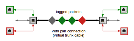
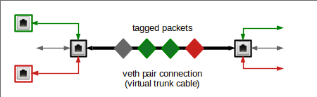
In VLANs packet transport is controlled on the link layer and not on the network layer of the TCP/IP protocol. An interesting question for all coming experiments will be, where and how the tagging of the Ethernet packets must occur. Experiment 4 will show that a virtual Linux bridge has a lot in common with real switches – and that in simple cases the bridge configuration alone can define the required VLANs.
Note that we will not use any firewall rules to achieve the separation of the network traffic! However, be aware of the fact that the prevention of ARP spoofing even in our simple scenario requires packet filtering (e.g. by netfilter iptables/ebtables rules).
Experiment 4
The experiment is illustrated in the upper left corner of the graphics below; we configure the area surrounded by the blue dotted line:
You recognize the drawing of our virtual test environment (discussed in the article 2). We set up (unnamed) network namespaces netns1, netns2, netns4, netns5 and of course netns3 with the help of commands discussed in article 1. Remember: The “names” netnx, actually, are hostnames! netns3 contains our bridge “brx“.
VLAN IDs and VLAN tags are numbers. But for visualization purposes you can imagine that we give Ethernet packets that shall be exchanged between netns1 and netns2 a green tag and packets which travel between netns4 and netns5 a pink tag. The small red line between the respective ports inside the bridge represents the separation of our two groups of network namespaces (or containers) via 2 VLANs. For the meaning of other colors around some plug symbols see the text below.
For connectivity tests we need to watch packets of the ARP (address
resolution) protocol and the propagation of ICMP packets. tcpdump will help us to identify such packets at selected interfaces.
Connect 4 network namespaces with the help of a (virtual) Linux bridge in a fifth namespace
As in our previous experiments (see post 2) we enter the following list of commands at a shell prompt. (You may just copy/paste them). The list is a bit lengthy, so you may have to scroll:
# set up namespaces
unshare --net --uts /bin/bash &
export pid_netns1=$!
nsenter -t $pid_netns1 -u hostname netns1
unshare --net --uts /bin/bash &
export pid_netns2=$!
unshare --net --uts /bin/bash &
export pid_netns3=$!
unshare --net --uts /bin/bash &
export pid_netns4=$!
unshare --net --uts /bin/bash &
export pid_netns5=$!

# assign different hostnames
nsenter -t $pid_netns1 -u hostname netns1
nsenter -t $pid_netns2 -u hostname netns2
nsenter -t $pid_netns3 -u hostname netns3
nsenter -t $pid_netns4 -u hostname netns4
nsenter -t $pid_netns5 -u hostname netns5

#set up veth devices
ip link add veth11 netns $pid_netns1 type veth peer name veth13 netns $pid_netns3
ip link add veth22 netns $pid_netns2 type veth peer name veth23 netns $pid_netns3
ip link add veth44 netns $pid_netns4 type veth peer name veth43 netns $pid_netns3
ip link add veth55 netns $pid_netns5 type veth peer name veth53 netns $pid_netns3

# Assign IP addresses and set the devices up
nsenter -t $pid_netns1 -u -n /bin/bash
ip addr add 192.168.5.1/24 brd 192.168.5.255 dev veth11
ip link set veth11 up
ip link set lo up
exit
nsenter -t $pid_netns2 -u -n /bin/bash
ip addr add 192.168.5.2/24 brd 192.168.5.255 dev veth22
ip link set veth22 up
ip link set lo up
exit
nsenter -t $pid_netns4 -u -n /bin/bash
ip addr add 192.168.5.4/24 brd 192.168.5.255 dev veth44
ip link set veth44 up
ip link set lo up
exit
nsenter -t $pid_netns5 -u -n /bin/bash
ip addr add 192.168.5.5/24 brd 192.168.5.255 dev veth55
ip link set veth55 up
ip link set lo up
exit

# set up the bridge
nsenter -t $pid_netns3 -u -n /bin/bash
brctl addbr brx
ip link set brx up
ip link set veth13 up
ip link set veth23 up
ip link set veth43 up
ip link set veth53 up
brctl addif brx veth13
brctl addif brx veth23
brctl addif brx veth43
brctl addif brx veth53
exit

lsns -t net -t uts
We expect that we can ping from each namespace to all the others. We open a subshell window (see the third post of the series), enter namespace netns5 there and ping e.g. netns2:
mytux:~ # nsenter -t $pid_netns5 -u -n /bin/bash
netns5:~ # ping 192.168.5.2 -c2
PING 192.168.5.2 (192.168.5.2) 56(84) bytes of data.
64 bytes from 192.168.5.2: icmp_seq=1 ttl=64 time=0.031 ms
64 bytes from 192.168.5.2: icmp_seq=2 ttl=64 time=0.029 ms

--- 192.168.5.2 ping statistics ---
2 packets transmitted, 2 received, 0% packet loss, time 999ms
rtt min/avg/max/mdev = 0.029/0.030/0.031/0.001 ms
So far so good.
Create and isolate two VLANs for two groups of network namespaces (or containers) via proper port configuration of a Linux bridge
We have not set up the ports of our bridge, yet, to handle different VLANs. A look into the rules discussed in the last post provides the necessary information, and we execute the following commands:
# set up 2 VLANs
nsenter -t $pid_netns3 -u -n /bin/bash
ip link set dev brx type bridge vlan_filtering 1
bridge vlan add vid 10 pvid untagged dev veth13
bridge vlan add vid 10 pvid untagged dev veth23
bridge vlan add vid 20 pvid
untagged dev veth43
bridge vlan add vid 20 pvid untagged dev veth53
bridge vlan del vid 1 dev brx self
bridge vlan del vid 1 dev veth13
bridge vlan del vid 1 dev veth23
bridge vlan del vid 1 dev veth43
bridge vlan del vid 1 dev veth53
bridge vlan show
exit
Note:
For working on the bridge’s Ethernet interface itself we need the “self” string.
Question: Where must and will VLAN tags be attached to network packets – inside or/and outside the bridge?
Answer: In our present scenario inside the bridge, only.
This is consistent with using the option “untagged” at all ports: Outside the bridge there are only untagged Ethernet packets.
The command “bridge VLAN show” gives us an overview over our VLAN settings and the corresponding port configuration:
netns3:~ # bridge vlan show
port    vlan ids
veth13   10 PVID Egress Untagged

veth23   10 PVID Egress Untagged

veth43   20 PVID Egress Untagged

veth53   20 PVID Egress Untagged

brx     None
netns3:~ #
In our setup VID 10 corresponds to the “green” VLAN and VID 20 to the “pink” one.
Please note that there is absolutely no requirement to give the bridge itself an IP address or to define VLAN sub-interfaces of the bridge’s own Ethernet interface. Treating and configuring the bridge itself as an Ethernet device may appear convenient and is a standard background operation of many applications, which configure bridges. E.g. of virt-manager. But in my opinion such an implicit configuration only leads to unclear and potentially dangerous situations for packet filtering. A bridge with an IP gets an additional and special, but fully operational interface to its environment (here to its network namespace) – besides the “normal” ports to clients. It is easy to forget this special interface. Actually, it even gets a default PVID and VID (value 1) assigned. But I delete these VID/PVID almost always to avoid any traffic at the bridges default interface. Personally, I use a bridge very, very seldom as an Ethernet device with an IP address. If I need a connection to the surrounding network namespace I use a veth device, instead. Then we have an explicitly defined port. In our experiment 4 such a connection is not required.
Testing the VLANs
Now we open 2 sub shell windows for entering our namespaces (in KDE e.g. by “konsole &>/dev/null &”).
First we watch traffic from 192.168.5.1 through veth43 in netns3 in one of our shells:
mytux:~ # nsenter -t $pid_netns4 -u -n /bin/bash
netns3:~ # tcpdump -n -i veth43  host 192.168.5.1 -e
tcpdump: verbose output suppressed, use -v or -vv for full protocol decode
listening on veth43, link-type EN10MB (Ethernet), capture size 262144 bytes
Then we open another shell and try to ping netns4 from netns1 :
mytux:~ # nsenter -t $pid_netns1 -u -n /bin/bash
netns1:~ # ping 192.168.5.4
PING 192.168.5.4 (192.168.5.4) 56(84) bytes of data.
^C
--- 192.168.5.4 ping statistics ---
2 packets transmitted, 0 received, 100% packet loss, time 1007ms
Nothing happens at veth43 in netns3! This was to be expected as our VLAN for VID 10, of course, is isolated from VLAN with VID 20.
However, if we watch traffic on veth23 in netns3 and ping in parallel for netns2 and later for netns4 from netns1, we get (inside netns1):
netns1:~ # ping 192.168.5.2
PING 192.168.5.2 (192.168.5.2) 56(84) bytes of data.
64 bytes from 192.168.5.2: icmp_seq=1 ttl=64 time=0.090 ms
64 bytes from 192.168.5.2: icmp_seq=2 ttl=64 time=0.064 ms
^C
--- 192.168.5.2 ping statistics ---
2 packets transmitted, 2 received, 0% packet loss, time 1000ms
rtt min/avg/max/mdev = 0.064/0.077/0.090/0.013 ms
nnetns1:~ # ^C
netns1:~ # ping 192.168.5.4
PING 192.168.5.4 (192.168.5.4) 56(84) bytes of data.
From 192.168.5.1 icmp_seq=1 Destination Host Unreachable
From 192.168.5.1 icmp_seq=2 Destination Host Unreachable
From 192.168.5.1 icmp_seq=3 Destination Host Unreachable
^C
--- 192.168.5.4 ping statistics ---
6 packets transmitted, 0 received, +3 errors, 100% packet loss, time 5031ms
pipe 3
At the same time in netns3:
netns3:~ # tcpdump -n -i veth23  host 192.168.5.1 -e
tcpdump: verbose output suppressed, use -v or -vv for full protocol decode
listening on veth23, link-type EN10MB (Ethernet), capture size 262144 bytes
16:13:59.748075 f2:3d:63:de:a8:41 > 6e:12:2e:cf:c1:25, ethertype IPv4 (0x0800), length 98: 192.168.5.1 > 192.168.5.2: ICMP echo request, id 29195, seq 1, length 64
16:13:59.748106 6e:12:2e:cf:c1:25 > f2:3d:63:de:a8:41, ethertype IPv4 (0x0800), length 98: 192.168.5.2 > 192.168.5.1: ICMP echo reply, id 29195, seq 1, length 64
16:14:00.748326 f2:3d:63:de:a8:41 > 6e:12:2e:cf:c1:25, ethertype IPv4 (0x0800), length 98: 192.168.5.1 > 192.168.5.2: ICMP echo request, id 29195, seq 2, length 64
16:14:00.748337 6e:12:2e:cf:c1:25 > f2:3d:63:de:a8:41, ethertype IPv4 (0x0800), length 98: 192.168.5.2 > 192.168.5.1: ICMP echo reply, id 29195, seq 2, length 64
16:16:48.630614 f2:3d:63:de:a8:41 > ff:ff:ff:ff:ff:ff, ethertype ARP (0x0806), length 42: Request who-has 192.168.5.4 tell 192.168.5.1, length 28
16:16:49.628213 f2:3d:63:de:a8:41 > ff:ff:ff:ff:ff:ff, ethertype ARP (0x0806), length 42: Request who-has 192.168.5.4 tell 192.168.5.1, length 28
16:16:50.628220 f2:3d:63:de:a8:41 > ff:ff:ff:ff:ff:ff, ethertype ARP (0x0806), length 42: Request who-has 192.168.5.4 tell 192.168.5.1, length 28
16:16:51.645477 f2:3d:63:de:a8:41 > ff:ff:ff:ff:ff:ff, ethertype ARP (0x0806), length 42: Request who-has 192.168.5.4 tell 192.168.5.1, length 28
16:16:52.644229 f2:3d:63:de:a8:41 > ff:ff:ff:ff:ff:ff, ethertype ARP (0x0806), length 42: Request who-has 192.168.5.4 tell 192.168.5.1, length 28
16:16:53.644171 f2:3d:63:de:a8:41 > ff:ff:ff:ff:ff:ff, ethertype ARP (0x0806), length 42: Request who-has 192.168.5.4 tell 192.168.5.1, length 28
^C
10 packets captured
10 packets received by filter
0 packets dropped by kernel
You may test the other communication channels in the same way. Obviously, we have succeeded in isolating a “green” communication area from a “pink” one! On the link layer level – i.e. despite the fact that all members of both VLANs belong to the same IP network class!
Note that even a user on the host can not see the traffic inside the two VLANs directly; he/she does not even see the network interfaces with “ip a s” as they all are located in network namespaces different from its own …
VLAN tags on packets outside the bridge?
Just for fun (and for the preparation of coming experiments) we want to try and assign a “brown” tag to packets outside the bridge, namely those moving along the veth connection line to netns2.
On real Ethernet devices you need to define sub-devices to achieve a VLAN tagging. Actually, this works with veth interfaces, too! With the following command list we extend each of our interfaces veth22 and veth23 by a sub-interface. We assign the IP address 192.168.5.2 afterwards to the sub-interface veth22.50 of veth22 (instead of veth22 itself). Instead of veth23 we then plug its new sub-interface into our virtual bridge to terminate the connection correctly.
# Replace veth22, veth23 with sub-interfaces
nsenter -t $pid_netns3 -u -n /bin/bash
brctl delif brx veth23
ip link add link veth23 name veth23.50 type vlan id 50
ip link set veth23.50 up
brctl addif brx veth23.50
exit
nsenter -t $pid_netns2 -u -n /bin/bash
ip addr del 192.168.5.2/24 brd 192.168.5.255 dev veth22
ip link
add link veth22 name veth22.50 type vlan id 50
ip addr add 192.168.5.2/24 brd 192.168.5.255 dev veth22.50
ip link set veth22.50 up
bridge vlan add vid 10 pvid untagged dev veth23.50
bridge vlan del vid 1 dev veth23.50
exit
The PVID/VID-setting is done for the new sub-interface “veth23.50” on the bridge! Note that the “green” VID 10 inside the bridge is different from the VLAN ID 50, which is used outside the bridge (“brown” tags). According to the rules presented in the last article this should not have any impact on our VLANs:
Tags of incoming packets entering the bridge via veth23 are removed and replaced the green tag (10) before forwarding occurs inside the bridge. Outgoing packets first get their green tag removed due to the fact that we have marked the port with the flag “untagged”. But on the outside of the bridge the veth sub-interface re-marks the packets with the “brown” tag.
We ping netns2
netns1:~ # ping 192.168.5.2 -c3
PING 192.168.5.2 (192.168.5.2) 56(84) bytes of data.
64 bytes from 192.168.5.2: icmp_seq=1 ttl=64 time=0.099 ms
64 bytes from 192.168.5.2: icmp_seq=2 ttl=64 time=0.055 ms
64 bytes from 192.168.5.2: icmp_seq=3 ttl=64 time=0.094 ms

--- 192.168.5.2 ping statistics ---
3 packets transmitted, 3 received, 0% packet loss, time 1998ms
rtt min/avg/max/mdev = 0.055/0.082/0.099/0.022 ms
netns1:~ #
and capture the respective packets at “veth23” with tcpdump:
netns3:~ # bridge vlan show
port    vlan ids
veth13   10 PVID Egress Untagged

veth43   20 PVID Egress Untagged

veth53   20 PVID Egress Untagged

brx     None
veth23.50        10 PVID Egress Untagged

netns3:~ # tcpdump -n -i veth23  host 192.168.5.1 -e
tcpdump: verbose output suppressed, use -v or -vv for full protocol decode
listening on veth23, link-type EN10MB (Ethernet), capture size 262144 bytes
17:38:55.962118 f2:3d:63:de:a8:41 > 6e:12:2e:cf:c1:25, ethertype 802.1Q (0x8100), length 102: vlan 50, p 0, ethertype IPv4, 192.168.5.1 > 192.168.5.2: ICMP echo request, id 1772, seq 1, length 64
17:38:55.962155 6e:12:2e:cf:c1:25 > f2:3d:63:de:a8:41, ethertype 802.1Q (0x8100), length 102: vlan 50, p 0, ethertype IPv4, 192.168.5.2 > 192.168.5.1: ICMP echo reply, id 1772, seq 1, length 64
17:38:56.961095 f2:3d:63:de:a8:41 > 6e:12:2e:cf:c1:25, ethertype 802.1Q (0x8100), length 102: vlan 50, p 0, ethertype IPv4, 192.168.5.1 > 192.168.5.2: ICMP echo request, id 1772, seq 2, length 64
17:38:56.961116 6e:12:2e:cf:c1:25 > f2:3d:63:de:a8:41, ethertype 802.1Q (0x8100), length 102: vlan 50, p 0, ethertype IPv4, 192.168.5.2 > 192.168.5.1: ICMP echo reply, id 1772, seq 2, length 64
17:38:57.960293 f2:3d:63:de:a8:41 > 6e:12:2e:cf:c1:25, ethertype 802.1Q (0x8100), length 102: vlan 50, p 0, ethertype IPv4, 192.168.5.1 > 192.168.5.2: ICMP echo request, id 1772, seq 3, length 64
17:38:57.960328 6e:12:2e:cf:c1:25 > f2:3d:63:de:a8:41, ethertype 802.1Q (0x8100), length 102: vlan 50, p 0, ethertype IPv4, 192.168.5.2 > 192.168.5.1: ICMP echo reply, id 1772, seq 3, length 64
17:39:00.976243 6e:12:2e:cf:c1:25 > f2:3d:63:de:a8:41, ethertype 802.1Q (0x8100), length 46: vlan 50, p 0, ethertype ARP, Request who-has 192.168.5.1 tell 192.168.5.2, length 28
17:39:00.976278 f2:3d:63:de:a8:41 > 6e:12:2e:cf:c1:25, ethertype 802.1Q (0x8100), length 46: vlan 50, p 0, ethertype ARP, Reply 192.168.5.1 is-at f2:3d:63:de:a8:41, length 28
Note the information ” ethertype 802.1Q (0x8100), length 46: vlan 50″ which proves the tagging with 50 outside the bridge.
Note further that we needed to capture on device veth23 – on device veth23.50 we do not see the tagging:
netns3:~ # tcpdump -n -i veth23.50  host 192.168.5.1 -e
tcpdump: verbose output suppressed, use -v or -vv for full protocol decode
listening on veth23.50, link-type EN10MB (Ethernet), capture size
262144 bytes
17:45:29.015840 f2:3d:63:de:a8:41 > 6e:12:2e:cf:c1:25, ethertype IPv4 (0x0800), length 98: 192.168.5.1 > 192.168.5.2: ICMP echo request, id 2222, seq 1, length 64
17:45:29.015875 6e:12:2e:cf:c1:25 > f2:3d:63:de:a8:41, ethertype IPv4 (0x0800), length 98: 192.168.5.2 > 192.168.5.1: ICMP echo reply, id 2222, seq 1, length 64
Can we see the tagging inside the bridge? Yes, we can:
netns3:~ # tcpdump -n -i brx  host 192.168.5.1 -e
tcpdump: verbose output suppressed, use -v or -vv for full protocol decode
listening on brx, link-type EN10MB (Ethernet), capture size 262144 bytes
17:51:41.563316 f2:3d:63:de:a8:41 > 6e:12:2e:cf:c1:25, ethertype 802.1Q (0x8100), length 102: vlan 10, p 0, ethertype IPv4, 192.168.5.1 > 192.168.5.2: ICMP echo request, id 2535, seq 1, length 64
17:51:41.563343 6e:12:2e:cf:c1:25 > f2:3d:63:de:a8:41, ethertype 802.1Q (0x8100), length 102: vlan 10, p 0, ethertype IPv4, 192.168.5.2 > 192.168.5.1: ICMP echo reply, id 2535, seq 1, length 64
17:51:42.562333 f2:3d:63:de:a8:41 > 6e:12:2e:cf:c1:25, ethertype 802.1Q (0x8100), length 102: vlan 10, p 0, ethertype IPv4, 192.168.5.1 > 192.168.5.2: ICMP echo request, id 2535, seq 2, length 64
17:51:42.562387 6e:12:2e:cf:c1:25 > f2:3d:63:de:a8:41, ethertype 802.1Q (0x8100), length 102: vlan 10, p 0, ethertype IPv4, 192.168.5.2 > 192.168.5.1: ICMP echo reply, id 2535, seq 2, length 64
17:51:43.561327 f2:3d:63:de:a8:41 > 6e:12:2e:cf:c1:25, ethertype 802.1Q (0x8100), length 102: vlan 10, p 0, ethertype IPv4, 192.168.5.1 > 192.168.5.2: ICMP echo request, id 2535, seq 3, length 64
17:51:43.561367 6e:12:2e:cf:c1:25 > f2:3d:63:de:a8:41, ethertype 802.1Q (0x8100), length 102: vlan 10, p 0, ethertype IPv4, 192.168.5.2 > 192.168.5.1: ICMP echo reply, id 2535, seq 3, length 64
17:51:46.576259 6e:12:2e:cf:c1:25 > f2:3d:63:de:a8:41, ethertype 802.1Q (0x8100), length 46: vlan 10, p 0, ethertype ARP, Request who-has 192.168.5.1 tell 192.168.5.2, length 28
17:51:46.576276 f2:3d:63:de:a8:41 > 6e:12:2e:cf:c1:25, ethertype 802.1Q (0x8100), length 46: vlan 10, p 0, ethertype ARP, Reply 192.168.5.1 is-at f2:3d:63:de:a8:41, length 28
^C
Note: “ethertype 802.1Q (0x8100), length 46: vlan 10”. Inside the bridge we have the tag 10 – as expected. In our setup the external VLAN tagging is irrelevant!
This enhances security: VLAN tags can be manipulated outside the bridge. But as such tags get stripped when packets enter the bridge via ports based on veth sub-interfaces, this won’t help an attacker so much …. :-).
For certain purposes we can (and will) use VLAN tagging also along certain connections outside the bridge – but the control and isolation of network paths between containers on one and the same virtualization host normally does not require VLAN tagging outside a bridge. The big exception is of course when routing to the outside world is required. But this is the topic of later blog posts.
If you like, you can now test that one can not ping e.g. netns5 from netns2. This will not be possible as inside the bridge packets from netns2 get tags for the VLAN ID 10 as we have seen – and neither the port based on veth43 nor the port for veth53 will allow any such packets to pass.
VLANs support security, but traffic separation alone is not sufficient. Some spoofing attack vectors would try to flood the bridge with wrong information about MACs. The dynamic learning of a port-MAC relation then becomes a disadvantage. One may think that the bridges’s internal tagging would nevertheless block a packet misdirection to the wrong VLAN. However, the real behavior may depend on details of the bridges’s handling of the protocol stacks and the point when tagging occurs. I do not understand enough, yet, about this. So, better work proactively:
There are parameters by which you can make the port-MAC relations almost static. Use them and implement netfilter rules in addition! You need such rules anyway to avoid ARP spoofing within each VLAN.
Traffic between VLANs?
If you for some reasons need to allow for traffic between you have to establish routing outside the bridge and limit the type of traffic allowed by packet filter rules. A typical scenario would be that some clients in one VLAN need access to services (special TCP ports) of a container in a network namespace attached to another VLAN. I do not follow this road here, yet, because right now I am more interested in isolation. But see the following links for examples of routing between VLANs :
https://serverfault.com/ questions/ 779115/ forward-traffic-between-vlans-with-iptables
https://www.riccardoriva.info/blog/?p=35
Conclusion
Obviously, we can use a virtual Linux bridge in a separate network namespace to isolate communication paths between groups of other network namespaces against each other. This can be achieved by making the bridge VLAN aware and by setting proper VIDs, PVIDs on the bridge ports of veth interfaces. Multiple VLANs can thus be establish by just one bride. We have shown that the separation works even if all members of both VLANs belong to the same IP network class.
We did not involve the bridge’s own Ethernet interface and we did not need any packet tagging outside the bridge to achieve our objective. In our case it was not necessary to define sub-interfaces on either side of our veth connections. But even if we had used sub-interfaces and tagging outside the bridge it would not have destroyed the operation of our VLANs. The bridge itself establishes the VLANs; thinking virtual VLANs means thinking virtual bridges/switches – at least since kernel 3.9!
If we associated the four namespaces with 4 LXC containers our experiment 4 would correspond to a typical scenario for virtual networking on a host, whose containers are arranged in groups. Only members of a group are allowed to communicate with each other. How about extending such a grouping of namespaces/containers to another host? We shall simulate such a situation in the next blog post …
Fun with veth-devices, Linux bridges and VLANs in unnamed Linux network namespaces – VI
Stay tuned !