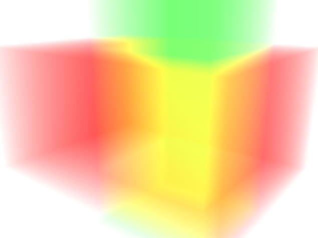
After two stressful months at my job I used part of my Christmas holidays to play a bit around with Blender. For me Blender has always been a fascinating tool to perform optical experiments with mirrors, lenses, light emitting gases, etc. It’s real fun … like in a virtual lab. See e.g. the image of two half-transparent cubes intersecting each other in an asymmetric way; the cubes were filled with volumetric gas emitting red and green light:

The idea for the experiment illustrated above arose in a discussion with a German artist (Michael Grossmann) about different kinds of color mixtures. The human eye and the neural networks behind it interpret a dense mixture of green and red light rays as yellow. This is true only for active light emitters, but not for passive reflective particles as used in painting. Think of pixels emitting light on a TV-screen: There neighboring red and green pixels create an impression of yellow.
In this present article series, however, I want to describe two experiments for highly reflective mirroring surfaces. I got the ideas from two real art installations. All credit must be given to the artists behind the original art objects:
One object is located in a sculpture park in Norway called “Kistefoss museum”. See https://www.kistefosmuseum.com/ sculpture/ the-sculpture-park. I warn you – a visit to this park is really expensive in my opinion (18 Euros per person + 8 Euros or more for parking. OK, the fact that enjoying modern art is a kind of luxury had to be expected in the richest country outside the EU. And, of course, Kistefoss is run by a private investor …. See https://www.kistefos.no/. Some things obviously never change during the history of capitalism. Presently the impression of art in original “nature” of an originally beautiful river valley is spoiled by a huge construction site for a 4 or 6 track autobahn bridge. Well, well – so much about the relation between art and capitalism.
Nevertheless – there are some really nice installations at Kistefoss to look at.
The object I refer to is named “S-Curve” and was made by the well known contemporary artist Anish Kapoor. See “https://www.kistefosmuseum.com/ sculptur/ s-curve” or google for “s-curve anish kapoor” and look at the images. The installation consists of a bent elongated rectangular metallic surface looking like a twisted curved band. Curved in two directions: The curvature on the left side of the s-curved band is concave, on the right side it is convex. I found this idea of combining reflective concave and convex mirror surfaces breathtakingly simple and impressive at the same time. The whole installation makes you think about the reality behind visual images triggered by some conceptional network in your brain. It reminded me of the old Platonic idea that our relation to the real world must be compared to a man sitting in a cave where he only sees shadows of a real world on a wall. Now, imagine a world where our cave walls where made of curved mirrors – how could we get a clue about the reality behind the strange reflections? Well, such questions seemingly trigger something inside physicists …
The second public installation is located in the Norwegian city of Drammen at a river bank. There you are confronted with highly reflective outer surfaces of two spheres on each side of the river. However, these spheres also have a kind of spherical indentation on their outer sides. Sometimes when the
sun is at the right position you can see strange ring like reflections of light in these indentations – with rater sharp edges. Similar disturbing effects can be seen when you put some intensive LED lamp outside and inside the sphere. Makes you wonder what kind of images an open half-sphere would create.
The question what a camera placed at different positions in front or inside a reflective open half-sphere is for many reasons interesting if you start thinking about it with some recovered school knowledge about optics. Three major points are:
- Things may appear to be located in front of the mirror surface.
- There is inversion. Reflected things appear upside down and left-right mirrored.
- In addition multiple reflections have to be taken into account in a half-sphere. Which is by the way the reason for multiple ring like reflections of distant bright light sources.
There is a phantastic video on Youtube “What Does It Look Like INSIDE a Spherical Mirror?” (https://www.youtube.com/watch?v=Y8c7TZx8HeY) which gives you a live impression of the strange things a concave mirror surface can do with light rays. Well, not everybody has the means to make or get a perfect mirroring half sphere. Or get some huge metal plates and deform them as a S-shaped cylindrical band. For us normal people Blender will have to do a job with virtual objects.
To raise your appetite I first want to present two preliminary rendered images from Blender. One just shows the reflections of some objects (cylinders, spheres, cones) placed in front of two plain cylindrical surfaces attached to each other. This is a first simplified approximation to the S-curve. But it already reveals some of the properties which we can expect to find on a twisted continuous metal structure like the S-curve of Mr. Kapoor.
The other image shows the reflections of some relatively small objects (again a sphere, a cone and a cylinder) positioned deep inside a concave half-sphere. This second picture indicates the complexity which multiple reflections within an open reflective half-sphere can create. We shall later enhance the artificial scenes displayed below by additional mirrors (flat, cylindrical and spherical) behind the camera. Another goal is a movie with the camera slowly moving in and out of an open half-sphere.
It took me a while to create the pictures below as I needed to adapt to some changes in the Blender tool set and to master some specific tasks of modeling. For the present project I use version 2.82 of Blender which came together with Opensuse Leap 15.3 on my laptop. The last time I worked with blender I had a version around 2.0. Especially the problem how to construct perfect reflecting surfaces of cones, cylinders and spheres required some investigation. Also we need to choose the “cycles” rendering engine to get satisfactory results. Note also that the “metallicity” parameter used these days was set to 1 in the pictures below. This gives you an unrealistic loss free reflection. I shall discuss these points in detail in forthcoming articles.
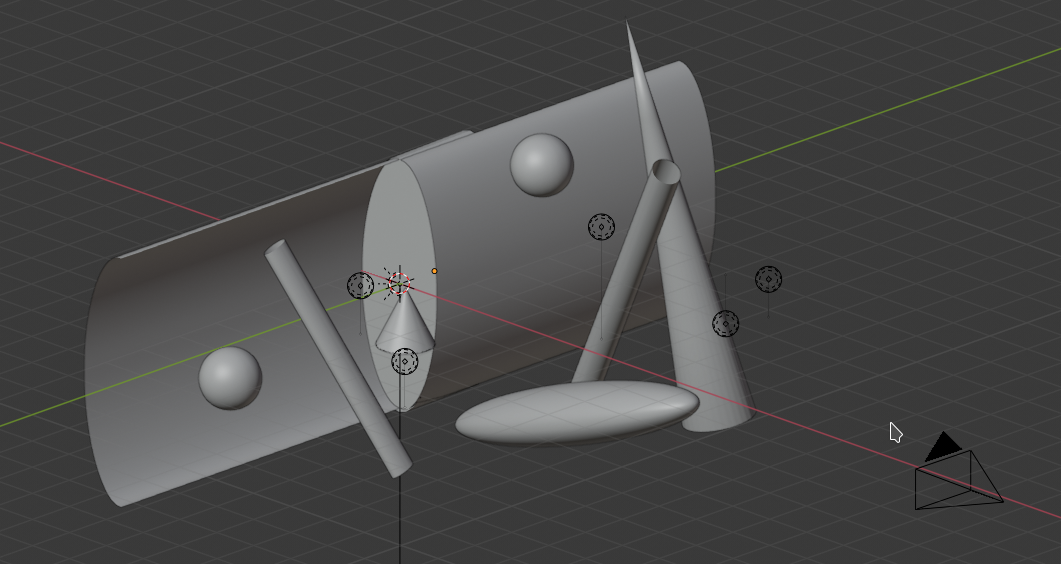
Two cylindrical surfaces with some objects in front of them
The following image from Blender’s viewport interface clearly reveals the shape and form of the cylindrical surfaces. Also the objects creating the reflections are shown. The reader will also find some point like light sources spread around in the scene.
And with a simple background the rendered result of ray tracing looks like:

What we can see here on the left side is that concave mirror surfaces can create some illusionary, rather deceptive images with shapes very different from the original object from which the light rays are emitted (by a first reflection of light from the surroundings).
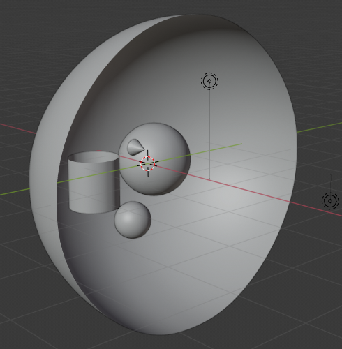
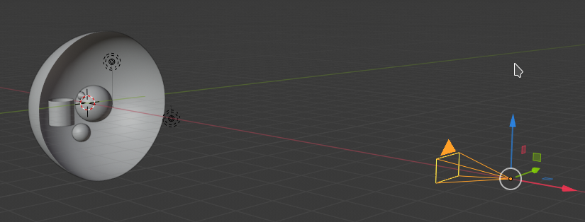
The half sphere with some objects in it
The first two pictures below show the basic spatial setup of the next scene with blender.
The rendered result looks like:

You see the distinct ring-like reflection zones in the outer parts? This is the result of multiple reflections – we can count at least 9 reflections before the reflection zones become indistinguishable. The image also displays the rich complexity reflections by the inner zones of the half-sphere and multiple reflections between the objects themselves can create for a viewer outside the sphere. In forthcoming experiments we shall create pictures also for positions of the camera inside the sphere.
In my next post
Blender – complexity inside spherical and concave cylindrical mirrors – II – a step towards the S-curve
I will make a first step to reconstruct something like the real smooth S-curve within Blender. Stay tuned. And a happy new year 2022 to everybody!