
My present post series on veth devices and Linux network namespaces continues articles I have written in 2017 about virtual networking and veth based connections. The last two posts of the present series
- More fun with veth, network namespaces, VLANs – IV – L2-segments, same IP-subnet, ARP and routes
- More fun with veth, network namespaces, VLANs – V – link two L2-segments of the same IP-subnet by a routing network namespace
were a kind of excursion: We studied the effects of routes on ARP-requests in network namespaces where two or more L2-segments of a LAN terminated – with all IPs in both L2-segments belonging to one and the same IP subnet. So far, the considered segments in this series were standard L2-segments, not VLAN segments.
Despite being instructive, scenarios with multiple standard L2-segments attached to a namespace (or virtualized host) are a bit academic. However, when you replace the virtual L2-segments by private virtual VLAN segments we come to more relevant network configurations. A namespace or a virtualized host with multiple attached VLAN segments is not academic. Even without forwarding and even if the namespace got just one IP. We speak of a virtual “multi-homed” namespace (or virtualized host) connected to multiple VLAN segments.
What could be relevant examples?
- Think of a virtual host that administers other guest systems in various private VLANs of a virtualization server! To achieve this we need routes in the multi-homed host, but no forwarding.
- On the other side think of a namespace/host where multiple VLANs terminate and where groups of LAN segments must be connected to each other or to the outer world. In this case we would combine private VLANs with forwarding; the namespace would become a classic router for virtual hosts loacted in different VLANs.
The configuration of virtual private VLAN scenarios based on Linux veth and bridge devices is our eventual objective. In forthcoming posts we will consider virtual VLANs realized with the help of veth subdevices. Such VLANs follow the IEEE 802.1q standard for the Link layer. And regarding VLAN-aware bridges we may refer to RFC5517. A Linux (virtual) bridge fulfills almost all of the requirements of this RFC.
This very limited set of tools gives us a choice between many basic options of setting up a complex VLAN landscape. Different options to configure Linux bridge ports and/or VLAN aware veth endpoints in namespaces extends the spectrum of decisions to be made. An arangement of multiple cascading bridges may define a complex hierarchcal topology. But there are other factors, too. Understanding the influence of routes and of Linux kernel parameters on the path and propagation of ARP and ICMP requests in virtual LANs with VLANs and multi-homed namespaces (or hosts) can become crucial regarding both functionality and weak points of different solutions.
In this post we start with briefly discussing different basic options of VLAN creation. We then look closer at configuration variants for veth VLAN aware interfaces inside a namespace. The results will prepares us for two very simple VLAN scenarios that will help us to investigate the impact of routes and kernel parameters in the next two posts. In later posts I will turn to the port configuration of Linux bridges for complex VLAN solutions.
Private VLANs and veth endpoints
We speak of private VLANs because we want to separate packet traffic between different groups of hosts within a LAN-segment – on the Link layer. This requires that the packets get marked and processed according to these marks. In a 802.1q compliant VLAN the packets get VLAN tags, which identify a VLAN ID [VID] in special data sections of Ethernet packets. By analyzing these tags by and in VLAN aware devices we can filter packets and thus subdivide the original LAN segment into different VLAN-segments. Private VLAN segments form a Link layer broadcast domain (here: Ethernet broadcast domain) of their own.
The drawing below shows tagged packets (diamond like shape) moving along one and the same veth connection line. The colors represent a certain VID.
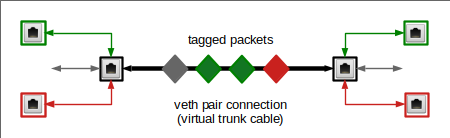
We see some VLAN aware network devices on both sides. They send and receive packets with certain tags only. A veth endpoint can be supplemented with such VLAN aware subdevices. The device in the middle may instead handle untagged packets only. But we could also have something like this:
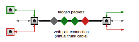
Here on the right side a typical “trunk interface” transports all kinds of tagged and untagged packets into a target space – which could be a namespace or the inner part of a bridge. We will see that such a trunk interface is realized by a standard veth endpoint.
Basic VLAN variants based on veths and Linux bridges
Linux bridge ports for attached VLAN aware or unaware devices can be configured in various ways to tag or de-tag packets. Via VID-related filters the bridge can establish and control allowed or disallowed connections between its ports, all on the Link layer. Based on veths and Linux bridges there are four basic ways to set up to (virtual) VLAN solutions:
- We can completely rely on the tagging and traffic separation abilities of Linux bridges. All namespaces and hosts would be connected to the bridge via veth lines and devices that transport untagged packets, only. The bridge then defines the VLANs of a LAN-segment.
- We can start with VLAN separation already in the multi-homed namespace/host via VLAN aware sub-devices of veth endpoints and connect respective VLAN-aware devices or a trunk device of a veth peer device to the bridge. These options require different settings on bridge ports.
- We can combine approaches (1) and (2).
- We can connect different namespaces directly via VLAN aware veth peer devices.
(4) is a possible way to realize VLANs. But it is not an elegant approach and rather difficult to maintain. However, we can use approach (4) for testing elementary conditions of packet transport and the impact of kernel rules for source validation or filtering of packets.
(3) provides a multitude of options both regarding VLAN topology as well as the handling of multi-homed namespaces/hosts. But, in my opinion, it also allows for (relatively) secure and tailor-made solutions for your specific purposes.
Complexity and the dangers of unintended crossover traffic, of asymmetric traffic and/or of failing ARP
A namespace can be made VLAN aware by different veth endpoint configurations. Details of the IP assignment will play a role. Together with different methods of attaching veth devices to a VLAN aware Linux bridge it is difficult to keep up control and overview. The complexity is enhanced by the impact of routes on basic ARP and ICMP/IP packet paths in multi-homed namespaces or hosts. In addition the settings of kernel parameters may block or modify ARP replies to requests and thus influence IP traffic.
In any case we would like separate the traffic between different VLANs as completely as possible without preventing traffic along intended allowed paths. Starting with ARP. There are some problems with this when we have to deal with one or more multi-homed namespaces or hosts. As we have seen in previous posts we are in danger to create unintended crossover traffic or asymmetric packet flow – at least on the level of ARP. And the problem may become bigger if we wanted to represent the multi-homed namespace/host via exactly one IP to different VLANs. The experiments in the previous posts have taught us that we need to be prepared.
Therefore, Before we can turn to complex VLAN scenarios based on veth devices and VLAN-aware Linux bridges, we must first have a close look at VLAN interface configurations of veth endpoints in a namespace. Such a namespace may become multi-homed with respect to multiple attached VLANs even if got just one IP addresses. Afterward we need to study how routes affect both the creation and paths of ARP and ICMP packets in such multi-homed and VLAN aware namespaces.
Due to the combined effects of different variants of IP-assignment to VLAN aware veth interfaces, due to details of route settings and also due to the impact of certain Linux kernel parameters this is going to be a cumbersome endeavor. We have to approach our goal step by step. In the end we will find that already basic communication abilities of even simple example configurations via ARP and ICMP are determined by routes, source validation by the Linux kernel and other ARP-related kernel parameters:
- ARP and ICMP requests: Impact of routes on the selection of a VLAN interface and VLAN segment amongst multiple available ones for emission of the respective Ethernet broadcasts and unicasts,
- ARP and ICMP replies: Impact of routes and kernel parameters on the evaluation of received requests, on the creation of ARP and ICMP replies and on the emission of respective unicast packets. The reply packets will alos be evaluated with respect to their source at the requestor.
The lessons we learn will enable us to configure and understand more realistic and bridge based scenarios.
But as said: step by step … Below I first want to remind you of basic configuration options for veth devices with multiple sub-interfaces that can handle tagged packets from and for different VLAN segments. We will in particular consider different options for assigning IP addresses to veth endpoints with VLAN subdevices.
VLAN aware subdevices of a veth
A veth connection realizes a kind of direct connection line between two endpoints, also called peer devices. You can imagine the connection line as a tunnel with an instantaneous transport capacity. A packet created and send at one endpoint is directly available at the peer device. I will use the terms “veth endpoint”, “veth peer device” or simply “veth peer” as synonyms when I refer to one of the two virtual network devices making up a veth connection.
In an old post I have already described what we can do to create a VLAN interface of a veth endpoint: We take a veth peer device, create a subdevice of type “vlan” and add a VID to it.
Let us name the two endpoints of an example veth connection veth1 and veth2. Then supplementing veth1 with a virtual VLAN interface requires a command sequence like
netns1:~ # ip link add link veth1 name veth1.10 type vlan id 10
netns1:~ # ip link set veth1 up
netns1:~ # ip link set veth1.10 up
By repeating these commands for further VLAN IDs [VIDs] veth1 we will create multiple distinct interfaces for different VLANs (see a graphics below for two subdevices). Remember that the main device and its subdevices may become fully operational only if also the status of its peer device is set to up.
Packets moving from VLAN related veth subdevices to the veth connection line (and the other peer) will get a tag corresponding to the VID. We can use a veth VLAN subdevice to create packets intended to reach members of specific VLAN segments.
The veth endpoint is VLAN-aware in the sense that a particular VLAN subdevice only receives and handles packets which arrive from the veth connection line with a tag fitting the subdevice’s defining VID. A packet with a tag not fitting to any of the VLAN subdevices is dropped.
The main endpoint device transports tagged and untagged packets in both directions – out of the namespace and from a connected peer into the namespace. Arriving tagged packets from a peer located outside the namespace first pass the main interface which transfers them for further processing to the veth’s VLAN subdevices.
What about the other peer device of a veth connection when one of its endpoints becomes VLAN aware? The other endpoint may have or may not have VLAN subdevices! Its behavior will differ accordingly. A peer without VLAN subdevices would e.g. make sense as a trunk connector to a bridge and just transmit any kind of packet. However, it would not lead to a working connection if it were directly placed in another namespaces.
Veth VLAN interfaces – tagging and de-tagging of packets at ingress and egress
Below I will often use the term VLAN interface of a veth endpoint when I refer to a peer’s subdevice of type “vlan”.
The difference between interface and device is just a logical one: Interface refers to a border which a packet must traverse into and out from a (V)LAN segment or into/out of/from inner parts of a bridge. Device, in my thinking, refers more to the application of the rules of the network protocol stack to the packets.
In addition, when speaking of an interface, I abstract from the complexity of the interaction between a subdevice and the main veth peer device. I regard the whole veth endpoint as a unit having multiple interfaces for packet transport. Some interfaces (namely those related to subdevices of type “vlan”) trigger a tagging or de-tagging process: When an originally untagged packet coming from a namespace passes the VLAN interface it gets tagged and afterward it moves through main veth endpoint device into the connection line. When instead a tagged packet moves from the connection line through the main device to the VLAN interface it gets eventually untagged when being transferred into the receiving namespace.
Note:
You should not assume that packets entering a veth peer’s VLAN interface from a namespace or packets leaving via a VLAN interface into a namespace have a tag. The interface just defines a certain “access port” to a veth peer device which leads to tagging at packet ingress. Tagging occurs somewhere during the transfer between sub- and main-device. We need not care about the details.
Neither should you assume that a packet leaving a veth peer’s VLAN interface to a namespace or a bridge is tagged. We will actually see (with the help of tcpdump) that originally tagged packets which enter a peer device through the veth connection line have their tags stripped off when they pass the VLAN interface into the surrounding namespace. The namespace itself is always confronted with untagged packets.
The following drawing shows schematically whats going on:
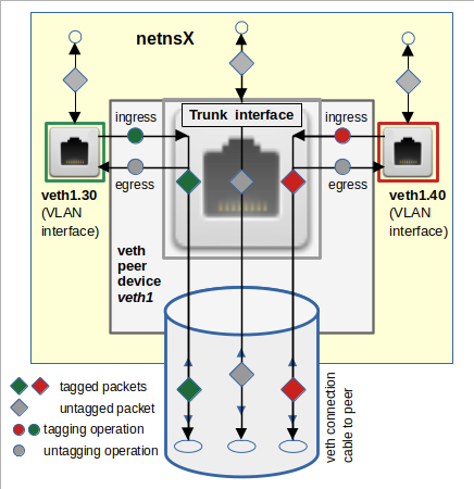
Why is the tagging and de-tagging behavior important for veth based VLAN configurations?
- A namespace can (normally) only handle untagged packets. Thus a trunk interface spitting out tagged packets into a namespace will not be of any use for almost all practical purposes.
- In case of multiple VLAN interfaces of a veth endpoint the namespace, i.e. the Linux kernel handling it, has no tag available to select a specific interface for sending a reply to an ARP-request which originally arrived as a tagged packet at the veth endpoint. It must base its decision which interface to use on other criteria.
- The port settings at a Linux bridge must account for the tag-related behavior of attached veth VLAN interfaces.
- It will later make a substantial difference whether we attach a veth VLAN interface to a Linux bridge or whether we just attach a pure veth endpoint device (without subdevices).
“Trunk interface” of a veth endpoint
Independent of defined VLAN interfaces we can always send a packet directly through the main device of a veth peer. In the illustration above veth1 remains a fully capable (virtual) Ethernet device – whether we add subdevices or or not. I will call the original interface of a peer device, e.g. veth1, the “main interface” or “trunk interface” of a veth endpoint.
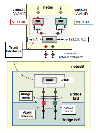
Why “trunk”? Well, the main interface will transport packets with various VLAN tags to and from its VLAN interfaces. But, as we will see, the main interface itself remains fully capable to emit and receive untagged packets. In addition there is a relation to trunk ports of a bridge/switch: If you think of a veth device then one peer vethA may be located in a namespace and may have subdevices. The other endpoint vethB may, however, not have VLAN interfaces and we may have directly attached it to a Linux bridge. There it would be associated with a classical trunk port. See the drawing below.
I will come back to details of bridge port configurations both for veth VLAN interfaces and trunk interfaces in a later post.
IP address assignment to veth subdevices – options for the case of all local and destination IPs being members of the same IP subnet
We imagine again a namespace or host which shall administer hosts in different VLANs. With all IPs of all communication partners belonging to one and the same IP subnet.
We have a variety of configuration options for such a namespace. The first two “basic” options below do not use veth VLAN interfaces. The other options employ tagging inside the namespace by veth subdevices. With the exception of one option all alternatives will lead to a multi-homed namespace.
Basic option 1: Working with the just the main interface of one standard veth endpoint
This option is extremely simple: We just use one veth endpoint without VLAN subdevices, i.e. more or less a standard NIC, in the namespace and assign an IP:
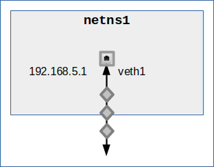
Then all the packets transported by this NIC are, of course, untagged – in both directions. VLAN traffic completely depends on the setup of a VLAN aware bridge.
Now, you may ask: How can we get a working multi-VLAN communication out of such a setup? Especially, if you know that a bridge port can assign only one VID (via a PVID parameter) to a previously untagged packet moving into the bridge? Although you may find deviating opinions on the Internet, this is fully possible. We come back to such a scenario when we dive deep into configuration options of a Linux bridge in forthcoming posts.
The weak point of this option regarding a strict separation of VLAN traffic is: You cannot select between different paths to different VLAN segments. Among other things one consequence is: Any ARP request will reach all of the hosts in all the VLAN segments you want to talk to. So, at least some crossover traffic can not be avoided. From a hacker’s perspective you may therefore get the information that certain IPs exist somewhere – and that our namespace has access to these IPs. This helps both with the so called lateral move of hackers, but it also provides information which can be valuable in MiM-attacks.
Basic option 2: Working with the main interfaces of multiple veth endpoints
We can extend basic option (1) by adding as many veth endpoints as we need to equip the namespace with border NICs to the various VLANs realized by a bridge. For just two VLANs this might look like this:
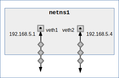
We still depend on a proper bridge configuration. But now we can assign different IPs to the available interfaces. I.e. we can address the two VLAN segments we want to talk to via different border NICs. All in all this reminds us very much of the scenario of a namespace with two connected L2-segments. We know already what we have to do to force ARP and ICMP requests into the right (VLAN) segment: We must define detailed routes.
Option 3: Use multiple veth endpoints each with a single VLAN interface
So far, we have not used VLAN interfaces of veth endpoints at all. A very simple variant which we shall use in an experiment in the next post is the following
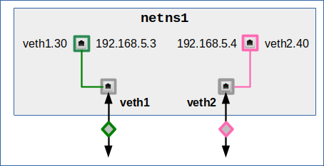
Another sub-option is:
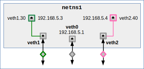
veth1 and veth2 only play a role as a transparent intermediate transport object for tagged packets. However, we can use veth0 to send and receive untagged packets from standard hosts or namespaces in our IP subnet. This option in a way is very similar to option 2. The difference is that we already send or receive tagged packets via the VLAN interfaces.
I do not show the commands for setting all devices up. Do not forget to set the peer devices of the main endpoint devices up, too. We afterward can get the second sub-option by
netns1:~ # ip addr add 192.168.5.1/24 dev veth0
netns1:~ # ip addr add 192.168.5.3/24 dev veth1.30
netns1:~ # ip addr add 192.168.5.4/24 dev veth2.40
netns1:~ # ip route del 192.168.5.0/24 dev veth1.30
netns1:~ # ip route del 192.168.5.0/24 dev veth2.40
netns1:~ # ip route add 192.168.5.30/32 dev veth1.30
netns1:~ # ip route add 192.168.5.31/32 dev veth1.30
netns1:~ # ip route add 192.168.5.40/32 dev veth2.40
netns1:~ # ip route add 192.168.5.41/32 dev veth2.40
Note that the 2nd and 3rd command establish routes to 192.168.5.0/24 which we must delete afterward.
netns1:~ # ip a
1: lo: <LOOPBACK,UP,LOWER_UP> mtu 65536 qdisc noqueue state UNKNOWN group default qlen 1000
    link/loopback 00:00:00:00:00:00 brd 00:00:00:00:00:00
    inet 127.0.0.1/8 scope host lo
       valid_lft forever preferred_lft forever
2: veth1@if2: <BROADCAST,MULTICAST,UP,LOWER_UP> mtu 1500 qdisc noqueue state UP group default qlen 1000
    link/ether ca:88:49:cd:c3:a6 brd ff:ff:ff:ff:ff:ff link-netnsid 0
3: veth1.30@veth1: <BROADCAST,MULTICAST,UP,LOWER_UP> mtu 1500 qdisc noqueue state UP group default qlen 1000
    link/ether ca:88:49:cd:c3:a6 brd ff:ff:ff:ff:ff:ff
    inet 192.168.5.3/24 scope global veth1.30
       valid_lft forever preferred_lft forever
5: veth0@if5: <BROADCAST,MULTICAST,UP,LOWER_UP> mtu 1500 qdisc noqueue state UP group default qlen 1000
    link/ether 0e:c1:07:3b:c1:19 brd ff:ff:ff:ff:ff:ff link-netnsid 0
    inet 192.168.5.1/24 scope global veth0
       valid_lft forever preferred_lft forever
6: veth2@if6: <BROADCAST,MULTICAST,UP,LOWER_UP> mtu 1500 qdisc noqueue state UP group default qlen 1000
    link/ether d2:03:09:5f:ef:c5 brd ff:ff:ff:ff:ff:ff link-netnsid 0
7: veth2.40@veth2: <BROADCAST,MULTICAST,UP,LOWER_UP> mtu 1500 qdisc noqueue state UP group default qlen 1000
    link/ether d2:03:09:5f:ef:c5 brd ff:ff:ff:ff:ff:ff
    inet 192.168.5.4/24 scope global veth2.40
       valid_lft forever preferred_lft forever
netns1:~ #
Regarding the VLAN interfaces we have defined 2 groups of destination hosts in different VLAN segments. Why would the VLAN interfaces be used for these particular destinations? Well, remember the rule of “Longest Prefix Matching“.
netns1:~ # ip route show table all
192.168.5.0/24 dev veth0 proto kernel scope link src 192.168.5.1
192.168.5.30 dev veth1.30 scope link
192.168.5.31 dev veth1.30 scope link
192.168.5.40 dev veth2.40 scope link
192.168.5.41 dev veth2.40 scope link
local 127.0.0.0/8 dev lo table local proto kernel scope host src 127.0.0.1
local 127.0.0.1 dev lo table local proto kernel scope host src 127.0.0.1
broadcast 127.255.255.255 dev lo table local proto kernel scope link src 127.0.0.1
local 192.168.5.1 dev veth0 table local proto kernel scope host src 192.168.5.1
local 192.168.5.3 dev veth1.30 table local proto kernel scope host src 192.168.5.3
local 192.168.5.4 dev veth2.40 table local proto kernel scope host src 192.168.5.4
broadcast 192.168.5.255 dev veth1.30 table local proto kernel scope link src 192.168.5.3
broadcast 192.168.5.255 dev veth2.40 table local proto kernel scope link src 192.168.5.4
broadcast 192.168.5.255 dev veth0 table local proto kernel scope link src 192.168.5.1
netns1:~ #
We nevertheless have to trust in a proper configuration of a Linux bride to get no VLAN crossing traffic there.
Option 4: Assign a central IP to the main (trunk) interface and share it indirectly with the VLAN interfaces
The variants presented above were simple to understand in so far as all the interfaces of a veth endpoint (main and VLAN interfaces) got an individual IP. This made them to standard NICs and we got control over ARP and ICMP packet flow going out from the namespace.
A “problem”, which both option 2 and 3 share, is that we cannot present our namespace to other destinations by just one IP.
However, to achieve this objective, we can use a somewhat strange property of veth endpoint: It can “share” the IP of its central main device with its VLAN interfaces. So let us equip our namespace with just one veth endpoint having two (ore more) VLAN interfaces. And then we assign an IP address just to the main (trunk) interface:
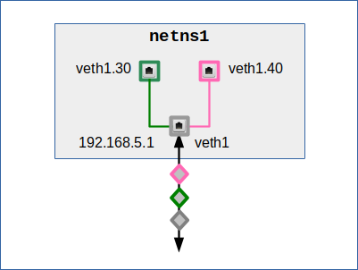
This option requires the following address and route settings to specific VLAN destinations – in my example I just use 4 such destinations:
netns1:~ # ip addr add 192.168.5.0/24 dev veth1
netns1:~ # ip route add 192.168.5.3/32 dev veth1.30
netns1:~ # ip route add 192.168.5.33/32 dev veth1.30
netns1:~ # ip route add 192.168.5.4/32 dev veth1.40
netns1:~ # ip route add 192.168.5.44/32 dev veth1.40
netns1:~ # ip a
1: lo: <LOOPBACK,UP,LOWER_UP> mtu 65536 qdisc noqueue state UNKNOWN group default qlen 1000
    link/loopback 00:00:00:00:00:00 brd 00:00:00:00:00:00
    inet 127.0.0.1/8 scope host lo
       valid_lft forever preferred_lft forever
2: veth1@if2: <BROADCAST,MULTICAST,UP,LOWER_UP> mtu 1500 qdisc noqueue state UP group default qlen 1000
    link/ether e6:8f:6b:0a:6b:fb brd ff:ff:ff:ff:ff:ff link-netnsid 0
    inet 192.168.5.1/24 brd 192.168.5.255 scope global veth1
       valid_lft forever preferred_lft forever
3: veth1.30@veth1: <BROADCAST,MULTICAST,UP,LOWER_UP> mtu 1500 qdisc noqueue state UP group default qlen 1000
    link/ether e6:8f:6b:0a:6b:fb brd ff:ff:ff:ff:ff:ff
4: veth1.40@veth1: <BROADCAST,MULTICAST,UP,LOWER_UP> mtu 1500 qdisc noqueue state UP group default qlen 1000
    link/ether e6:8f:6b:0a:6b:fb brd ff:ff:ff:ff:ff:ff
netns1:~ #
As we will see in future experiments, this can become a fully functional solution – with a bridge, but also for direct connections between different network namespaces. (In the latter case we have to invest some effort in topology. It is much easier done with a Linux bridge.)
Basically, we can exchange tagged and untagged packets with other namespaces. Most IPs in our IP subnet can be addressed with untagged packets via the trunk interface. As said, we have defined 4 destination IPs (in two groups) which shall be addresses via the VLAN interfaces, i.e. with tagged packets.
As we will confirm later by experiments, this option is somewhat tricky to handle. The saved effort regarding IP address assignment must be compensated by very careful route settings – not only in our multi-homed namespace, but also in the destination namespaces.
The reason is that in modern Linux systems “source validation” by the kernel is activated. This may include a check whether we can expect the type of packet (e.g. a broadcast packet) from the source IP. I see you frowning – but yes, this affects ARP, too. And we might get system messages regarding “martian sources” for ARP request or reply packets.
The reason for these potential problems is that the VLAN-interfaces in our approach do not get marked as receivers for broadcasts – even if we set a route pointing to this interface:
netns1:~ # ip route show table all
192.168.5.0/24 dev veth1.30 scope link
local 127.0.0.0/8 dev lo table local proto kernel scope host src 127.0.0.1
local 127.0.0.1 dev lo table local proto kernel scope host src 127.0.0.1
broadcast 127.255.255.255 dev lo table local proto kernel scope link src 127.0.0.1
local 192.168.5.1 dev veth1 table local proto kernel scope host src 192.168.5.1
broadcast 192.168.5.255 dev veth1 table local proto kernel scope link src 192.168.5.1
netns1:~ #
You see that only the main trunk interface has a route entry for broadcasts. We will see in further posts that this point really can cause severe problems. Even if ARP-requests are answered in one direction, they might not in the reverse direction. This configuration option requires fully symmetric reverse routes in all the namespaces (hosts) which we address with tagged packets.
Option 5: Assign the same IP to all interfaces
For a namespace or virtualized host, where two VLANs start or end, it might not be completely wrong to just present it to the different rivate VLAN-segments by just one IP. The named source evaluation potential problem of option 4 leads us to the following question:
Could we assign the same IP to all the different interfaces of a veth endpoint – as stupid as this might sound?
Yes, we can! In our example:
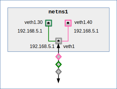
netns1:~ # ip addr add 192.168.5.1/24 dev veth1
netns1:~ # ip addr add 192.168.5.1/24 dev veth1.30
netns1:~ # ip addr add 192.168.5.1/24 dev veth1.40
netns1:~ # ip route del 192.168.5.0/24 dev veth1.30
netns1:~ # ip route del 192.168.5.0/24 dev veth1.40
netns1:~ # ip route add 192.168.5.3/32 dev veth1.30
netns1:~ # ip route add 192.168.5.33/32 dev veth1.30
netns1:~ # ip route add 192.168.5.4/32 dev veth1.40
netns1:~ # ip route add 192.168.5.44/32 dev veth1.40
The deletion commands are required to remove routes which are generated by default. We again have set different routes to two pairs of example hosts which we want to address via different VLAN connections.
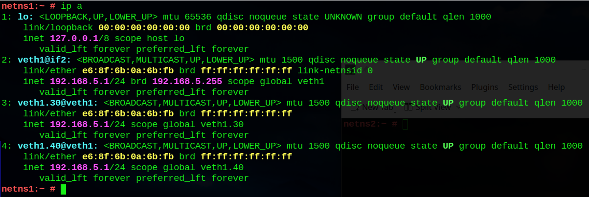
netns1:~ # ip a
1: lo: <LOOPBACK,UP,LOWER_UP> mtu 65536 qdisc noqueue state UNKNOWN group default qlen 1000
    link/loopback 00:00:00:00:00:00 brd 00:00:00:00:00:00
    inet 127.0.0.1/8 scope host lo
       valid_lft forever preferred_lft forever
2: veth1@if2: <BROADCAST,MULTICAST,UP,LOWER_UP> mtu 1500 qdisc noqueue state UP group default qlen 1000
    link/ether e6:8f:6b:0a:6b:fb brd ff:ff:ff:ff:ff:ff link-netnsid 0
    inet 192.168.5.1/24 brd 192.168.5.255 scope global veth1
       valid_lft forever preferred_lft forever
3: veth1.30@veth1: <BROADCAST,MULTICAST,UP,LOWER_UP> mtu 1500 qdisc noqueue state UP group default qlen 1000
    link/ether e6:8f:6b:0a:6b:fb brd ff:ff:ff:ff:ff:ff
    inet 192.168.5.1/24 scope global veth1.30
       valid_lft forever preferred_lft forever
4: veth1.40@veth1: <BROADCAST,MULTICAST,UP,LOWER_UP> mtu 1500 qdisc noqueue state UP group default qlen 1000
    link/ether e6:8f:6b:0a:6b:fb brd ff:ff:ff:ff:ff:ff
    inet 192.168.5.1/24 scope global veth1.40
       valid_lft forever preferred_lft forever
netns1:~ #
netns1:~ # ip route show table all
192.168.5.0/24 dev veth1 scope link
192.168.5.3 dev veth1.30 scope link
192.168.5.4 dev veth1.40 scope link
192.168.5.33 dev veth1.30 scope link
192.168.5.44 dev veth1.40 scope link
local 127.0.0.0/8 dev lo table local proto kernel scope host src 127.0.0.1
local 127.0.0.1 dev lo table local proto kernel scope host src 127.0.0.1
broadcast 127.255.255.255 dev lo table local proto kernel scope link src 127.0.0.1
local 192.168.5.1 dev veth1 table local proto kernel scope host src 192.168.5.1
local 192.168.5.1 dev veth1.30 table local proto kernel scope host src 192.168.5.1
local 192.168.5.1 dev veth1.40 table local proto kernel scope host src 192.168.5.1
broadcast 192.168.5.255 dev veth1 table local proto kernel scope link src 192.168.5.1
broadcast 192.168.5.255 dev veth1.30 table local proto kernel scope link src 192.168.5.1
broadcast 192.168.5.255 dev veth1.40 table local proto kernel scope link src 192.168.5.1
netns1:~ #
You see the disadvantages?
The first point is: Under normal circumstances assigning one and the same IP to two different NICs (with different MACs) would be regarded as a mistake. Well, what saves us here is the point that the MAC is the same for all interfaces of the veth endpoint! We just emphasize the basic symmetry and “ambiguity” already present in the setup of option 4.
The second point is: As in option 4 the effort to maintain all routes can explode. These options are useful only for automated setups via scripts and/or a small number of specific hosts which we want to reach with tagged packets only! (Note that in a non-forwarding situation PROXY ARP does not help to reduce the number of routes to maintain).
Option 6: Assign the same IP to the VLAN interfaces only
Option 7 is just a variant of option 5. We simply omit assigning a general route for 192.168.50/24 to the trunk interface. This means that all hosts that we want to communicate with must get a specific route via one of the VLAN interfaces. I omit the screenshots for this option.
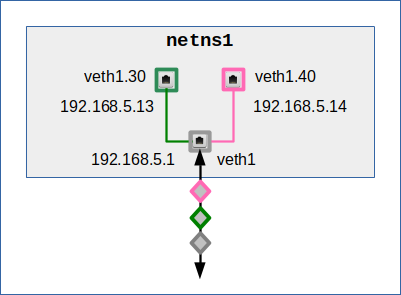
Option 7: Assign different IPs to the VLAN interfaces and the trunk interface
This option realizes the thought that we might want to make the namespace (or host) reachable from different VLAN segments via different target IPs. For example:
netns1:~ # ip addr add 192.168.5.1/24 dev veth1
netns1:~ # ip addr add 192.168.5.13/24 dev veth1.30
netns1:~ # ip addr add 192.168.5.14/24 dev veth1.40
netns1:~ # ip route del 192.168.5.0/24 dev veth1.30
netns1:~ # ip route del 192.168.5.0/24 dev veth1.40
netns1:~ # ip route add 192.168.5.3/32 dev veth1.30
netns1:~ # ip route add 192.168.5.4/32 dev veth1.40
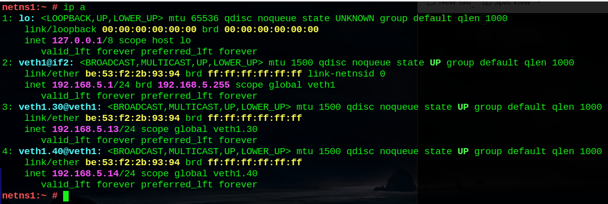
netns1:~ # ip a
1: lo: <LOOPBACK,UP,LOWER_UP> mtu 65536 qdisc noqueue state UNKNOWN group default qlen 1000
    link/loopback 00:00:00:00:00:00 brd 00:00:00:00:00:00
    inet 127.0.0.1/8 scope host lo
       valid_lft forever preferred_lft forever
2: veth1@if2: <BROADCAST,MULTICAST,UP,LOWER_UP> mtu 1500 qdisc noqueue state UP group default qlen 1000
    link/ether e6:8f:6b:0a:6b:fb brd ff:ff:ff:ff:ff:ff link-netnsid 0
    inet 192.168.5.1/24 brd 192.168.5.255 scope global veth1
       valid_lft forever preferred_lft forever
3: veth1.30@veth1: <BROADCAST,MULTICAST,UP,LOWER_UP> mtu 1500 qdisc noqueue state UP group default qlen 1000
    link/ether e6:8f:6b:0a:6b:fb brd ff:ff:ff:ff:ff:ff
    inet 192.168.5.13/24 scope global veth1.30
       valid_lft forever preferred_lft forever
4: veth1.40@veth1: <BROADCAST,MULTICAST,UP,LOWER_UP> mtu 1500 qdisc noqueue state UP group default qlen 1000
    link/ether e6:8f:6b:0a:6b:fb brd ff:ff:ff:ff:ff:ff
    inet 192.168.5.14/24 scope global veth1.40
       valid_lft forever preferred_lft forever
netns1:~ #
netns1:~ # ip route show table all
192.168.5.0/24 dev veth1 scope link
192.168.5.3 dev veth1.30 scope link
192.168.5.4 dev veth1.40 scope link
local 127.0.0.0/8 dev lo table local proto kernel scope host src 127.0.0.1
local 127.0.0.1 dev lo table local proto kernel scope host src 127.0.0.1
broadcast 127.255.255.255 dev lo table local proto kernel scope link src 127.0.0.1
local 192.168.5.1 dev veth1 table local proto kernel scope host src 192.168.5.1
local 192.168.5.13 dev veth1.30 table local proto kernel scope host src 192.168.5.13
local 192.168.5.14 dev veth1.40 table local proto kernel scope host src 192.168.5.14
broadcast 192.168.5.255 dev veth1 table local proto kernel scope link src 192.168.5.1
broadcast 192.168.5.255 dev veth1.30 table local proto kernel scope link src 192.168.5.13
broadcast 192.168.5.255 dev veth1.40 table local proto kernel scope link src 192.168.5.14
netns1:~ #
We shall investigate this option in detail in an experiment of a forthcoming post.
Option 8: Assign different IPs to the VLAN interfaces, only
Option 8 is just a variant of option 7. We just omit using the trunk interface for commnication. All hosts that we want to communicate with must get a specific route through one of the VLAN interfaces.
Destination IPs in other IP subnets
We do not need to cover this problem separately. Whenever we have different IP subnets then we address different LAN-segments (with their specific VLANs). We would use different veth devices (with and without VLAN subdevices) to realize the required connections. And maybe use multiple bridges, too. But otherwise everything we said above remains valid.
The interesting point about such a bit more complex scenarios is forwarding:
How must we set up routes such that a group of members of a VLAN in one LAN-segment attached to the namespace can only talk to members of a certain VLAN group in another segment? We will cover such scenarios in other posts.
Ambiguities in multi-homed namespaces
As we saw most configuration options above lead to multiple active network devices in a namespace connected to VLANs. The namespace, therefore, would become multi-homed. From the namespace’s perspective this automatically leads to a basic ambiguity: Which of the available interfaces should be selected for the emission of ICMP and ARP request or reply packets to reach hosts in the right VLAN segment or a segment for untagged communication?
This problem appears already on the level of ARP packets. From our experiences with multi-homed namespaces that were connected to multiple standard L2-segments, we would assume that this problem is solved by routes. However, for some of the named veth configuration options we will be confronted with the additional problem of source verification by the kernel.
Also note that an ambiguity may already become relevant in case of a single veth endpoint with just one VLAN subdevice. The reason is that we still have the endpoint’s main trunk device available for potential packet emission.
Conclusion
Veth subdevices allow for an astonishing diversity of endpoint configurations in a namespace which shall communicate with different attached VLAN segments. All the discussed variants must be complemented by a fitting configuration of the second veth peer device in a different namespace or at a bridge port.
Most of the presented configuration options characterize a multi-homed namespace or host. We expect that resulting ambiguities for packet emission must be resolved by defining proper routes – even if when all hosts we want to communicate with are members of the same IP subnet.
In my next post
I will test a first very simple VLAN based on veth endpoints. And I guarantee: We will experience some surprises ….