With this post I start a new series on the topic of virtual networks which we can create on a Linux virtualization host with commonly available and relatively simple standard tools. Lately, I have received relatively many questions of blog readers on this topic and meanwhile gathered enough new stuff that setting up a second post series seemed to be appropriate.
Introduction
Modern Linux systems use virtualization. This includes the use of containers as well as KVM-based virtual guest systems. Even in small companies a system admin will organize virtual clients and servers in groups. She/he will put virtualized guest systems into virtual network segments – often coinciding with IP-subnets. As Linux offers several classes of virtual switches the resulting virtual network can reach the same complexity as a real network.
Regarding security such a virtual network requires the application of all the measures which we take and apply in a real network environment. Single virtualized Linux hosts or groups of such hosts must be protected against each other. The dictum to follow is: Assume that the attacker is already somewhere on site.
Therefore, on the one hand the admin has to fully implement security appliances as e.g. firewalls and IDS systems on all virtualized hosts and at key points in the network. On the other hand it may be required to isolate groups of virtualized hosts and their group-internal communication against members of other groups. You normally would use IP-subnets and (V)LAN-segments plus routers and firewalls to achieve this.
Virtual VLANs for the isolation of groups of virtualized hosts
Virtual VLANs support the isolation of certain groups of virtualized hosts on the Link layer, i.e. even within a defined IP-subnet. VLANs define separate Ethernet broadcast domains on an otherwise normal LAN-segment. VLANs together with VLAN-aware switches may therefore help to reduce the overall network traffic and, at the same time, protect the communication inside VLAN-segments. But VLANs also introduce a new level of complexity for virtual networking.
The additional complexity has three aspects:
- The commands for the setup of a virtual network may strongly depend on the Linux tool set used.
- The configuration of virtual bridges/switches may differ from that of commercially available HW-based L2/L3-switches.
- At hosts (or Linux network namespaces) with multiple attached (V)LAN-segments ambiguities regarding the choice of a proper interface for sending elementary packets may come up. Veth devices with VLAN interfaces almost naturally produce such a kind of ambiguity.
- In some situation with ICMP- and ARP-requests and replies the Linux kernel may run through a specific chain of decisions regarding the transmission of VLAN-tagged packets through a particular VLAN-interface among multiple available ones. This chain may depend upon the type of virtual network interface or of the type of virtual bridge/switch used.
Hosts (or namespaces) with multiple attached (V)LAN-segments are critical points in a network. They require a careful configuration, e.g. regarding routes. This is valid for virtual networks, too. Remember that a such a host or namespace with multiple (V)LAN-segments need not be a router. It could just be a host responsible for the administration of other hosts in different (V)LAN-segments. In any case one needs to get a clear idea about the flow of key protocol packets at such hosts or network namespaces.
Namespaces instead of hosts for virtual (V)LAN planning and testing
Planning and testing a secure and segmented virtual network is a major task. A quick method to test the basic (V)LAN-segment layout would be very welcome. In case that you are just interested in the communication between hosts or segments without caring about details of the OS setup of a container or a KVM guest, then configuring a set of Linux network namespaces coupled by Linux bridges and veth devices may reduce your work load for testing significantly. A network namespace can replace or represent a virtualized Linux host in very many aspects regarding network traffic.
Older posts series of 2017 and motivation for a continuation
I have already written some posts series on virtualized (V)LANs and the usage of veth-devices, network namespaces and Linux bridges. See e.g.
Fun with veth-devices, Linux bridges and VLANs in unnamed Linux network namespaces – I
and
Linux bridges – can iptables be used against MiM attacks based on ARP spoofing ? – I
plus related posts.
The motivation behind the first of the named series was the definition of separate packet paths in complex virtual VLANs based on Linux bridges. Amongst other measures VLAN tagging at bridge ports is a central method to define certain allowed and disallowed paths for the propagation of Ethernet packets between virtual hosts or network namespaces within a given IP-subnet. Additional iptables, ebtables or nftables rules may help to control the traffic between certain bridge-ports and the segments behind them.
However, my old series did not fully cover some interesting points at namespaces where multiple VLAN lines terminate.
I want to mention that some really clever and serious questions of a reader, Joshua Greenberg, motivated me to consider related problems at namespaces with and without forwarding between VLAN-segments once again. His questions concerning some of my old statements gave me a bit of a headache – in particular with respect to ARP and routes. We agreed upon that some of the questions could only be answered by further experiments. So, many thanks to Joshua for giving me a push to turn my head towards virtual networking again.
This new post series deepens and extends the discussion of VLAN-related information given in my older post series. Among other things I will have a closer look on scenarios in which two or more separate LAN- and VLAN-segments are connected to a namespace with routing rules. All NICs will have IPs of one and the same IP-subnet (C-class net). In addition the behavior of ARP and ICMP packets on Linux bridges with iptables and ebtables rules will be analyzed.
On our way I will give you further simple examples for virtualized network setups – including VLANs – based on very elementary and generally available Linux tools (see below for a short list). The posts will again demonstrate how to use these tools to quickly define a segmented (V)LAN environment. But I will look deeper into some aspects than before – and thereby answer some open questions of readers. For example, I will have a look on some Linux kernel parameters.
Although I will repeat some basic points, my older posts are not obsolete. In particular a view into the introductory posts of the first series may be worth it. There I have given some basic information on veths and Linux bridges. I have also defined VLAN-configuration rules for bridge ports. These rules will be used in the present series, too.
In other posts of the previous series some special, but simple configurations were analyzed. The discussions there may help you to understand the new lines of thoughts in the forthcoming posts better. And I will also come back to the relatively big scenario discussed in my old post series.
Restrictions to simple virtual devices
This post series is definitely related to Linux systems. I do not care about MS Windows. Linux offers a big palette of tools and different virtual devices for virtual networking. I will restrict all efforts and considerations to a simple set of tools:
- Linux network namespaces (with routing capabilities),
- Linux virtual bridges,
- Ethernet-capable devices,
- Linux veth devices (with two peer devices and the capability to support VLAN sub-devices),
- iptables and ebtables as packet filters.
- Some real Ethernet NIC with contact to a real network segment and a router to the Internet.
All these elements should be available on a modern Linux system.
Focus on ARP and ICMP as key protocols at critical points with potential ambiguities
To set a focus for this new post series I will analyze predominantly ARP and ICMP traffic at critical places in our virtual network, e.g. at network namespaces where multiple (V)LAN segments come together. Other critical points mark the transition to real networks in some forwarding namespaces.
The experiments will cast light on possible ambiguities which arise due to spanning a IP-subnet over multiple L2-segments or over multiple VLAN segments. We will see that the capability of veth devices to support virtual VLANs introduces a basic ambiguity which the Linux kernel has to resolve – even on the level f the ARP protocol. We will in particular analyze the role of routes at such points and – as dubious as it may sound – the impact of routes on ARP traffic.
Open points of my previous post series and related questions
Both of my old post series on virtual networking got a long way, but were not finalized. I briefly outline some of the questions that remained open.
Multiple L2-segments attached to a common network namespace
I define a L2-segment as a LAN-segment, in which packets on the Link Layer travel freely. A L2-segment forms an Ethernet broadcast domain; Ethernet broadcast packets reach all NICs attached to a L2-segment. A good introduction to L1- and L2-segments and related Ethernet broadcasts is given here. Note that a complexly and hierarchically structured L2-segment may be created by connecting real or virtual linear Ethernet bus-lines by Linux bridges.
An exciting area of unusual scenarios opens up when so called L2-segments do not coincide with logical IP sub-nets.
Multiple different and originally separated virtual L2-segments with IPs of the same IP-subnet may be coupled by routing namespaces or (VLAN-aware) bridges/switches. On one side we may e.g. have a namespace with two attached standard L2-segments where untagged packets flow. What happens with ARP requests and replies in such a namespace?
On the other side NICs attached to one and the same L2-segment may belong to different IP sub-nets. Which on first sight appears to be a stupid mis-configuration; but such configurations may occur for a variety of reasons. What about ARP then?
What about VLANs across segments belonging to different logical IP sub-nets? Do such configurations make sense at all?
Termination of multiple VLANs via related sub-devices of veth endpoints in a network namespace
Two separated L2-segments may have NICs with IPs belonging to one and the same IP network class. The attentive reader of my 2017 series has of course noted that this was the case in all VLAN scenarios discussed at that time. Actually, this was the clue of the setups:
I used VLANs to isolate packet paths within one and the same IP sub-net ( a class C net) and within originally coherent L2-segments against each other. This worked out pretty well – as e.g. experiments with ICMP packets demonstrated.
However, I admit that I should have analyzed virtual veth connections which support multiple VLANs more thoroughly for some of my scenarios discussed in 2017. In particular a closer look at ARP-traffic in scenarios where a single veth-endpoint puts multiple VLAN-related sub-devices into one and the same target namespace (or into a bridge) would have been helpful. A discussion would probably have to avoid confusion of several readers regarding the impact of routes on ARP packets.
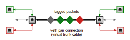
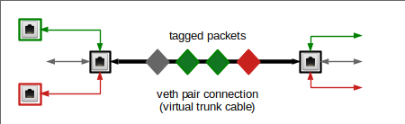
Before you think this topic may be boring, note that a veth endpoint device itself may get just one IP-address which it shares between all of its VLAN sub-interfaces and its trunk interface. See e.g. post. We will in addition find that a veth endpoint has just one MAC – which is also shared amongst all sub-interfaces. So the MAC/IP-tuple is not a unique identifier for any of a veth’s VLAN-interfaces or its neutral trunk interface. This is a major deviation from normal non-tagging NICs!
Thus, a VLAN-aware veth endpoint comes with multiple tagging NIC devices which cannot be identified by a MAC/IP-tuple alone. Somehow we (or more precisely some network namespaces) need additional rules to control the selection of a specific VLAN interface, such that our Ethernet packets get the right VLAN tag (VID) and propagate through the right VLAN to a target IP address.
In this context the coupling of network layer 2 (Link layer) to layer 3 (IP or network layer) is of special interest. Layer coupling by evaluating information about IP/MAC-relations is done by the ARP protocol. We all know that ARP is often used in hacker attacks. So it might be a good idea to know what happens with ARP in routing namespaces with multiple VLAN aware veth-end-points, a multitude of VLAN-interfaces and maybe a common NIC to reach real network segments. This is a major objective of this post series:
We want to thoroughly understand what ARP packets (requests and replies) do in the Linux network namespace with multiple available VLAN interfaces, but with just one IP/MAC-tuple shared between these interfaces.
In my old posts I speculated that ICMP and ARP answers in such unclear situations may depend on defined routes in the namespace. We shall find out in how far this is true by two corresponding experiments. As a contrast we will also look at situations where we give each of the VLAN-interfaces and individual IP address.
Connection of the virtual LAN to real LANs and the Internet
Scenarios with some ambiguities regarding packet paths are also of interest when traffic of different virtual VLANs must be directed to or through a common namespace which contains both VLAN end-points and a real NIC; the latter to enable communication to the outside world of a Linux virtualization host. Such a namespace would be a routing and forwarding one.
The connection of (virtual) VLANs to external real (physical) networks via namespaces that contain one or more real NICs were unfortunately not discussed in my old post series. (I had to work on project for a customer at this point). It is not at all clear whether we can separate the traffic between the VLANs and the outer world without the help of firewalls. In this context we may also have to look closer at the relation of VLANs to IP-subnets.
Bridges, iptables, VLANs and ARP
Readers have also sent me questions regarding VLAN-aware bridges and the propagation of ARP requests and ARP answer packets when IPtables rules control the packet traffic between bridge ports via “physdev“-related commands. What about tagged packets on a bridge with filtering IPtables rules?
Summary
Linux network namespaces, virtual Linux bridges and veth network devices make it possible to realize complex virtual network scenarios on a virtualization host – including virtual VLANs. Also virtual networks must be well protected against hacker attacks. Therefore, we should first understand packet transport through virtual (V)LAN devices and in particular across Linux bridges sufficiently well. Critical points are virtualized hosts or namespaces with multiple attached (V)LAN segments. Ambiguities regarding the packet path may come up, in particular in namespaces with multiple veh-based VLAN-interfaces.
Linux network namespaces and veths allow us to study packet transfer on different OSI layers in elementary network scenarios for L2-segments with and without virtualized VLANs in detail. The questions which remained open in my old post series and some new questions of readers invite us to study a bunch of further scenarios in a new post series.
In the next post
More fun with veth, network namespaces, VLANs – II – two L2-segments attached to a common network namespace
I will pose and study a first scenario without VLANs and respective tags. I will just attach veth end-points of two otherwise separated L2-segments to a common network namespace. Nevertheless, this very simple experiment will shed some light on open questions regarding routes, ARP and ICMP requests and answers. It will also lead us to aspects of PROXY ARP in (routing and forwarding) network namespaces.