Fun with veth-devices, Linux bridges and VLANs in unnamed Linux network namespaces – V

In the previous posts of this series

  1. Fun with veth-devices, Linux bridges and VLANs in unnamed Linux network namespaces – I
  2. Fun with veth-devices, Linux bridges and VLANs in unnamed Linux network namespaces – II
  3. Fun with veth-devices, Linux bridges and VLANs in unnamed Linux network namespaces – III
  4. Fun with veth-devices, Linux bridges and VLANs in unnamed Linux network namespaces – IV

we laid the foundations for working with VLANs in virtual networks between different network namespaces – or containers, if you like.

In the last post (4) I provided rules and commands for establishing VLANs via the configuration of a virtual Linux bridge. We saw how we define VLANs and set VLAN IDs, e.g. with the help of sub-interfaces of veth pairs or at Linux bridge ports (VIDs, PVID).

We apply this knowledge now to build the network environment for an experiment 4, which we described already in the second post:

The objective of this experiment 4 is the setup of two separated virtual VLANs for 2 groups of 4 network namespaces (or containers) with the help of a Linux bridge in a separate fifth network namespace.

In VLANs packet transport is controlled on the link layer and not on the network layer of the TCP/IP protocol. An interesting question for all coming experiments will be, where and how the tagging of the Ethernet packets must occur. Experiment 4 will show that a virtual Linux bridge has a lot in common with real switches – and that in simple cases the bridge configuration alone can define the required VLANs.

Note that we will not use any firewall rules to achieve the separation of the network traffic! However, be aware of the fact that the prevention of ARP spoofing even in our simple scenario requires packet filtering (e.g. by netfilter iptables/ebtables rules).

Experiment 4

The experiment is illustrated in the upper left corner of the graphics below; we configure the area surrounded by the blue dotted line:

You recognize the drawing of our virtual test environment (discussed in the article 2). We set up (unnamed) network namespaces netns1, netns2, netns4, netns5 and of course netns3 with the help of commands discussed in article 1. Remember: The “names” netnx, actually, are hostnames! netns3 contains our bridge “brx“.

VLAN IDs and VLAN tags are numbers. But for visualization purposes you can imagine that we give Ethernet packets that shall be exchanged between netns1 and netns2 a green tag and packets which travel between netns4 and netns5 a pink tag. The small red line between the respective ports inside the bridge represents the separation of our two groups of network namespaces (or containers) via 2 VLANs. For the meaning of other colors around some plug symbols see the text below.

For connectivity tests we need to watch packets of the ARP (address
resolution) protocol and the propagation of ICMP packets. tcpdump will help us to identify such packets at selected interfaces.

Connect 4 network namespaces with the help of a (virtual) Linux bridge in a fifth namespace

As in our previous experiments (see post 2) we enter the following list of commands at a shell prompt. (You may just copy/paste them). The list is a bit lengthy, so you may have to scroll:

# set up namespaces 
unshare --net --uts /bin/bash &
export pid_netns1=$!
nsenter -t $pid_netns1 -u hostname netns1
unshare --net --uts /bin/bash &
export pid_netns2=$!
unshare --net --uts /bin/bash &
export pid_netns3=$!
unshare --net --uts /bin/bash &
export pid_netns4=$!
unshare --net --uts /bin/bash &
export pid_netns5=$!

# assign different hostnames  
nsenter -t $pid_netns1 -u hostname netns1
nsenter -t $pid_netns2 -u hostname netns2
nsenter -t $pid_netns3 -u hostname netns3
nsenter -t $pid_netns4 -u hostname netns4
nsenter -t $pid_netns5 -u hostname netns5

#set up veth devices 
ip link add veth11 netns $pid_netns1 type veth peer name veth13 netns $pid_netns3   
ip link add veth22 netns $pid_netns2 type veth peer name veth23 netns $pid_netns3
ip link add veth44 netns $pid_netns4 type veth peer name veth43 netns $pid_netns3
ip link add veth55 netns $pid_netns5 type veth peer name veth53 netns $pid_netns3

# Assign IP addresses and set the devices up 
nsenter -t $pid_netns1 -u -n /bin/bash
ip addr add 192.168.5.1/24 brd 192.168.5.255 dev veth11
ip link set veth11 up
ip link set lo up
exit
nsenter -t $pid_netns2 -u -n /bin/bash
ip addr add 192.168.5.2/24 brd 192.168.5.255 dev veth22
ip link set veth22 up
ip link set lo up
exit
nsenter -t $pid_netns4 -u -n /bin/bash
ip addr add 192.168.5.4/24 brd 192.168.5.255 dev veth44
ip link set veth44 up
ip link set lo up
exit
nsenter -t $pid_netns5 -u -n /bin/bash
ip addr add 192.168.5.5/24 brd 192.168.5.255 dev veth55
ip link set veth55 up
ip link set lo up
exit

# set up the bridge 
nsenter -t $pid_netns3 -u -n /bin/bash
brctl addbr brx  
ip link set brx up
ip link set veth13 up
ip link set veth23 up
ip link set veth43 up
ip link set veth53 up
brctl addif brx veth13
brctl addif brx veth23
brctl addif brx veth43
brctl addif brx veth53
exit

lsns -t net -t uts

We expect that we can ping from each namespace to all the others. We open a subshell window (see the third post of the series), enter namespace netns5 there and ping e.g. netns2:

mytux:~ # nsenter -t $pid_netns5 -u -n /bin/bash
netns5:~ # ping 192.168.5.2 -c2
PING 192.168.5.2 (192.168.5.2) 56(84) bytes of data.
64 bytes from 192.168.5.2: icmp_seq=1 ttl=64 time=0.031 ms   
64 bytes from 192.168.5.2: icmp_seq=2 ttl=64 time=0.029 ms   

--- 192.168.5.2 ping statistics ---
2 packets transmitted, 2 received, 0% packet loss, time 999ms                                        
rtt min/avg/max/mdev = 0.029/0.030/0.031/0.001 ms                                                    

So far so good.

Create and isolate two VLANs for two groups of network namespaces (or containers) via proper port configuration of a Linux bridge

We have not set up the ports of our bridge, yet, to handle different VLANs. A look into the rules discussed in the last post provides the necessary information, and we execute the following commands:

# set up 2 VLANs  
nsenter -t $pid_netns3 -u -n /bin/bash
ip link set dev brx type bridge vlan_filtering 1
bridge vlan add vid 10 pvid untagged dev veth13
bridge vlan add vid 10 pvid untagged dev veth23
bridge vlan add vid 20 pvid 
untagged dev veth43
bridge vlan add vid 20 pvid untagged dev veth53
bridge vlan del vid 1 dev brx self
bridge vlan del vid 1 dev veth13
bridge vlan del vid 1 dev veth23
bridge vlan del vid 1 dev veth43
bridge vlan del vid 1 dev veth53
bridge vlan show 
exit

Note:

For working on the bridge’s Ethernet interface itself we need the “self” string.

Question: Where must and will VLAN tags be attached to network packets – inside or/and outside the bridge?
Answer: In our present scenario inside the bridge, only.

This is consistent with using the option “untagged” at all ports: Outside the bridge there are only untagged Ethernet packets.

The command “bridge VLAN show” gives us an overview over our VLAN settings and the corresponding port configuration:

netns3:~ # bridge vlan show
port    vlan ids
veth13   10 PVID Egress Untagged   

veth23   10 PVID Egress Untagged

veth43   20 PVID Egress Untagged

veth53   20 PVID Egress Untagged

brx     None
netns3:~ # 

In our setup VID 10 corresponds to the “green” VLAN and VID 20 to the “pink” one.

Please note that there is absolutely no requirement to give the bridge itself an IP address or to define VLAN sub-interfaces of the bridge’s own Ethernet interface. Treating and configuring the bridge itself as an Ethernet device may appear convenient and is a standard background operation of many applications, which configure bridges. E.g. of virt-manager. But in my opinion such an implicit configuration only leads to unclear and potentially dangerous situations for packet filtering. A bridge with an IP gets an additional and special, but fully operational interface to its environment (here to its network namespace) – besides the “normal” ports to clients. It is easy to forget this special interface. Actually, it even gets a default PVID and VID (value 1) assigned. But I delete these VID/PVID almost always to avoid any traffic at the bridges default interface. Personally, I use a bridge very, very seldom as an Ethernet device with an IP address. If I need a connection to the surrounding network namespace I use a veth device, instead. Then we have an explicitly defined port. In our experiment 4 such a connection is not required.

Testing the VLANs

Now we open 2 sub shell windows for entering our namespaces (in KDE e.g. by “konsole &>/dev/null &”).

First we watch traffic from 192.168.5.1 through veth43 in netns3 in one of our shells:

mytux:~ # nsenter -t $pid_netns4 -u -n /bin/bash
netns3:~ # tcpdump -n -i veth43  host 192.168.5.1 -e
tcpdump: verbose output suppressed, use -v or -vv for full protocol decode  
listening on veth43, link-type EN10MB (Ethernet), capture size 262144 bytes   

Then we open another shell and try to ping netns4 from netns1 :

mytux:~ # nsenter -t $pid_netns1 -u -n /bin/bash 
netns1:~ # ping 192.168.5.4
PING 192.168.5.4 (192.168.5.4) 56(84) bytes of data.
^C
--- 192.168.5.4 ping statistics ---
2 packets transmitted, 0 received, 100% packet loss, time 1007ms    

Nothing happens at veth43 in netns3! This was to be expected as our VLAN for VID 10, of course, is isolated from VLAN with VID 20.

However, if we watch traffic on veth23 in netns3 and ping in parallel for netns2 and later for netns4 from netns1, we get (inside netns1):

netns1:~ # ping 192.168.5.2
PING 192.168.5.2 (192.168.5.2) 56(84) bytes of data.
64 bytes from 192.168.5.2: icmp_seq=1 ttl=64 time=0.090 ms  
64 bytes from 192.168.5.2: icmp_seq=2 ttl=64 time=0.064 ms
^C
--- 192.168.5.2 ping statistics ---
2 packets transmitted, 2 received, 0% packet loss, time 1000ms   
rtt min/avg/max/mdev = 0.064/0.077/0.090/0.013 ms
nnetns1:~ # ^C
netns1:~ # ping 192.168.5.4
PING 192.168.5.4 (192.168.5.4) 56(84) bytes of data.
From 192.168.5.1 icmp_seq=1 Destination Host Unreachable  
From 192.168.5.1 icmp_seq=2 Destination Host Unreachable
From 192.168.5.1 icmp_seq=3 Destination Host Unreachable
^C
--- 192.168.5.4 ping statistics ---
6 packets transmitted, 0 received, +3 errors, 100% packet loss, time 5031ms                          
pipe 3                                

At the same time in netns3:

netns3:~ # tcpdump -n -i veth23  host 192.168.5.1 -e
tcpdump: verbose output suppressed, use -v or -vv for full protocol decode
listening on veth23, link-type EN10MB (Ethernet), capture size 262144 bytes
16:13:59.748075 f2:3d:63:de:a8:41 > 6e:12:2e:cf:c1:25, ethertype IPv4 (0x0800), length 98: 192.168.5.1 > 192.168.5.2: ICMP echo request, id 29195, seq 1, length 64    
16:13:59.748106 6e:12:2e:cf:c1:25 > f2:3d:63:de:a8:41, ethertype IPv4 (0x0800), length 98: 192.168.5.2 > 192.168.5.1: ICMP echo reply, id 29195, seq 1, length 64
16:14:00.748326 f2:3d:63:de:a8:41 > 6e:12:2e:cf:c1:25, ethertype IPv4 (0x0800), length 98: 192.168.5.1 > 192.168.5.2: ICMP echo request, id 29195, seq 2, length 64   
16:14:00.748337 6e:12:2e:cf:c1:25 > f2:3d:63:de:a8:41, ethertype IPv4 (0x0800), length 98: 192.168.5.2 > 192.168.5.1: ICMP echo reply, id 29195, seq 2, length 64
16:16:48.630614 f2:3d:63:de:a8:41 > ff:ff:ff:ff:ff:ff, ethertype ARP (0x0806), length 42: Request who-has 192.168.5.4 tell 192.168.5.1, length 28
16:16:49.628213 f2:3d:63:de:a8:41 > ff:ff:ff:ff:ff:ff, ethertype ARP (0x0806), length 42: Request who-has 192.168.5.4 tell 192.168.5.1, length 28
16:16:50.628220 f2:3d:63:de:a8:41 > ff:ff:ff:ff:ff:ff, ethertype ARP (0x0806), length 42: Request who-has 192.168.5.4 tell 192.168.5.1, length 28
16:16:51.645477 f2:3d:63:de:a8:41 > ff:ff:ff:ff:ff:ff, ethertype ARP (0x0806), length 42: Request who-has 192.168.5.4 tell 192.168.5.1, length 28
16:16:52.644229 f2:3d:63:de:a8:41 > ff:ff:ff:ff:ff:ff, ethertype ARP (0x0806), length 42: Request who-has 192.168.5.4 tell 192.168.5.1, length 28
16:16:53.644171 f2:3d:63:de:a8:41 > ff:ff:ff:ff:ff:ff, ethertype ARP (0x0806), length 42: Request who-has 192.168.5.4 tell 192.168.5.1, length 28
^C
10 packets captured
10 packets received by filter
0 packets dropped by kernel

You may test the other communication channels in the same way. Obviously, we have succeeded in isolating a “green” communication area from a “pink” one! On the link layer level – i.e. despite the fact that all members of both VLANs belong to the same IP network class!

Note that even a user on the host can not see the traffic inside the two VLANs directly; he/she does not even see the network interfaces with “ip a s” as they all are located in network namespaces different from its own …

VLAN tags on packets outside the bridge?

Just for fun (and for the preparation of coming experiments) we want to try and assign a “brown” tag to packets outside the bridge, namely those moving along the veth connection line to netns2.

On real Ethernet devices you need to define sub-devices to achieve a VLAN tagging. Actually, this works with veth interfaces, too! With the following command list we extend each of our interfaces veth22 and veth23 by a sub-interface. We assign the IP address 192.168.5.2 afterwards to the sub-interface veth22.50 of veth22 (instead of veth22 itself). Instead of veth23 we then plug its new sub-interface into our virtual bridge to terminate the connection correctly.

# Replace veth22, veth23 with sub-interfaces 
nsenter -t $pid_netns3 -u -n /bin/bash
brctl delif brx veth23
ip link add link veth23 name veth23.50 type vlan id 50  
ip link set veth23.50 up
brctl addif brx veth23.50 
exit 
nsenter -t $pid_netns2 -u -n /bin/bash
ip addr del 192.168.5.2/24 brd 192.168.5.255 dev veth22
ip link 
add link veth22 name veth22.50 type vlan id 50
ip addr add 192.168.5.2/24 brd 192.168.5.255 dev veth22.50    
ip link set veth22.50 up
bridge vlan add vid 10 pvid untagged dev veth23.50
bridge vlan del vid 1 dev veth23.50
exit 

The PVID/VID-setting is done for the new sub-interface “veth23.50” on the bridge! Note that the “green” VID 10 inside the bridge is different from the VLAN ID 50, which is used outside the bridge (“brown” tags). According to the rules presented in the last article this should not have any impact on our VLANs:

Tags of incoming packets entering the bridge via veth23 are removed and replaced the green tag (10) before forwarding occurs inside the bridge. Outgoing packets first get their green tag removed due to the fact that we have marked the port with the flag “untagged”. But on the outside of the bridge the veth sub-interface re-marks the packets with the “brown” tag.

We ping netns2

netns1:~ # ping 192.168.5.2 -c3
PING 192.168.5.2 (192.168.5.2) 56(84) bytes of data.
64 bytes from 192.168.5.2: icmp_seq=1 ttl=64 time=0.099 ms  
64 bytes from 192.168.5.2: icmp_seq=2 ttl=64 time=0.055 ms
64 bytes from 192.168.5.2: icmp_seq=3 ttl=64 time=0.094 ms

--- 192.168.5.2 ping statistics ---
3 packets transmitted, 3 received, 0% packet loss, time 1998ms   
rtt min/avg/max/mdev = 0.055/0.082/0.099/0.022 ms
netns1:~ # 

and capture the respective packets at “veth23” with tcpdump:

netns3:~ # bridge vlan show
port    vlan ids
veth13   10 PVID Egress Untagged

veth43   20 PVID Egress Untagged

veth53   20 PVID Egress Untagged

brx     None
veth23.50        10 PVID Egress Untagged

netns3:~ # tcpdump -n -i veth23  host 192.168.5.1 -e
tcpdump: verbose output suppressed, use -v or -vv for full protocol decode
listening on veth23, link-type EN10MB (Ethernet), capture size 262144 bytes         
17:38:55.962118 f2:3d:63:de:a8:41 > 6e:12:2e:cf:c1:25, ethertype 802.1Q (0x8100), length 102: vlan 50, p 0, ethertype IPv4, 192.168.5.1 > 192.168.5.2: ICMP echo request, id 1772, seq 1, length 64   
17:38:55.962155 6e:12:2e:cf:c1:25 > f2:3d:63:de:a8:41, ethertype 802.1Q (0x8100), length 102: vlan 50, p 0, ethertype IPv4, 192.168.5.2 > 192.168.5.1: ICMP echo reply, id 1772, seq 1, length 64
17:38:56.961095 f2:3d:63:de:a8:41 > 6e:12:2e:cf:c1:25, ethertype 802.1Q (0x8100), length 102: vlan 50, p 0, ethertype IPv4, 192.168.5.1 > 192.168.5.2: ICMP echo request, id 1772, seq 2, length 64
17:38:56.961116 6e:12:2e:cf:c1:25 > f2:3d:63:de:a8:41, ethertype 802.1Q (0x8100), length 102: vlan 50, p 0, ethertype IPv4, 192.168.5.2 > 192.168.5.1: ICMP echo reply, id 1772, seq 2, length 64
17:38:57.960293 f2:3d:63:de:a8:41 > 6e:12:2e:cf:c1:25, ethertype 802.1Q (0x8100), length 102: vlan 50, p 0, ethertype IPv4, 192.168.5.1 > 192.168.5.2: ICMP echo request, id 1772, seq 3, length 64   
17:38:57.960328 6e:12:2e:cf:c1:25 > f2:3d:63:de:a8:41, ethertype 802.1Q (0x8100), length 102: vlan 50, p 0, ethertype IPv4, 192.168.5.2 > 192.168.5.1: ICMP echo reply, id 1772, seq 3, length 64
17:39:00.976243 6e:12:2e:cf:c1:25 > f2:3d:63:de:a8:41, ethertype 802.1Q (0x8100), length 46: vlan 50, p 0, ethertype ARP, Request who-has 192.168.5.1 tell 192.168.5.2, length 28
17:39:00.976278 f2:3d:63:de:a8:41 > 6e:12:2e:cf:c1:25, ethertype 802.1Q (0x8100), length 46: vlan 50, p 0, ethertype ARP, Reply 192.168.5.1 is-at f2:3d:63:de:a8:41, length 28  

Note the information ” ethertype 802.1Q (0x8100), length 46: vlan 50″ which proves the tagging with 50 outside the bridge.

Note further that we needed to capture on device veth23 – on device veth23.50 we do not see the tagging:

netns3:~ # tcpdump -n -i veth23.50  host 192.168.5.1 -e
tcpdump: verbose output suppressed, use -v or -vv for full protocol decode
listening on veth23.50, link-type EN10MB (Ethernet), capture size 
262144 bytes
17:45:29.015840 f2:3d:63:de:a8:41 > 6e:12:2e:cf:c1:25, ethertype IPv4 (0x0800), length 98: 192.168.5.1 > 192.168.5.2: ICMP echo request, id 2222, seq 1, length 64   
17:45:29.015875 6e:12:2e:cf:c1:25 > f2:3d:63:de:a8:41, ethertype IPv4 (0x0800), length 98: 192.168.5.2 > 192.168.5.1: ICMP echo reply, id 2222, seq 1, length 64

Can we see the tagging inside the bridge? Yes, we can:

netns3:~ # tcpdump -n -i brx  host 192.168.5.1 -e
tcpdump: verbose output suppressed, use -v or -vv for full protocol decode
listening on brx, link-type EN10MB (Ethernet), capture size 262144 bytes
17:51:41.563316 f2:3d:63:de:a8:41 > 6e:12:2e:cf:c1:25, ethertype 802.1Q (0x8100), length 102: vlan 10, p 0, ethertype IPv4, 192.168.5.1 > 192.168.5.2: ICMP echo request, id 2535, seq 1, length 64   
17:51:41.563343 6e:12:2e:cf:c1:25 > f2:3d:63:de:a8:41, ethertype 802.1Q (0x8100), length 102: vlan 10, p 0, ethertype IPv4, 192.168.5.2 > 192.168.5.1: ICMP echo reply, id 2535, seq 1, length 64
17:51:42.562333 f2:3d:63:de:a8:41 > 6e:12:2e:cf:c1:25, ethertype 802.1Q (0x8100), length 102: vlan 10, p 0, ethertype IPv4, 192.168.5.1 > 192.168.5.2: ICMP echo request, id 2535, seq 2, length 64
17:51:42.562387 6e:12:2e:cf:c1:25 > f2:3d:63:de:a8:41, ethertype 802.1Q (0x8100), length 102: vlan 10, p 0, ethertype IPv4, 192.168.5.2 > 192.168.5.1: ICMP echo reply, id 2535, seq 2, length 64
17:51:43.561327 f2:3d:63:de:a8:41 > 6e:12:2e:cf:c1:25, ethertype 802.1Q (0x8100), length 102: vlan 10, p 0, ethertype IPv4, 192.168.5.1 > 192.168.5.2: ICMP echo request, id 2535, seq 3, length 64   
17:51:43.561367 6e:12:2e:cf:c1:25 > f2:3d:63:de:a8:41, ethertype 802.1Q (0x8100), length 102: vlan 10, p 0, ethertype IPv4, 192.168.5.2 > 192.168.5.1: ICMP echo reply, id 2535, seq 3, length 64
17:51:46.576259 6e:12:2e:cf:c1:25 > f2:3d:63:de:a8:41, ethertype 802.1Q (0x8100), length 46: vlan 10, p 0, ethertype ARP, Request who-has 192.168.5.1 tell 192.168.5.2, length 28
17:51:46.576276 f2:3d:63:de:a8:41 > 6e:12:2e:cf:c1:25, ethertype 802.1Q (0x8100), length 46: vlan 10, p 0, ethertype ARP, Reply 192.168.5.1 is-at f2:3d:63:de:a8:41, length 28
^C

Note: “ethertype 802.1Q (0x8100), length 46: vlan 10”. Inside the bridge we have the tag 10 – as expected. In our setup the external VLAN tagging is irrelevant!

The separation of communication paths between different ports inside of the bridge can be controlled by the bridge setup alone – independent of any VLAN packet tagging, which may occur outside the bridge!

This enhances security: VLAN tags can be manipulated outside the bridge. But as such tags get stripped when packets enter the bridge via ports based on veth sub-interfaces, this won’t help an attacker so much …. :-).

For certain purposes we can (and will) use VLAN tagging also along certain connections outside the bridge – but the control and isolation of network paths between containers on one and the same virtualization host normally does not require VLAN tagging outside a bridge. The big exception is of course when routing to the outside world is required. But this is the topic of later blog posts.

If you like, you can now test that one can not ping e.g. netns5 from netns2. This will not be possible as inside the bridge packets from netns2 get tags for the VLAN ID 10 as we have seen – and neither the port based on veth43 nor the port for veth53 will allow any such packets to pass.

VLANs support security, but traffic separation alone is not sufficient. Some spoofing attack vectors would try to flood the bridge with wrong information about MACs. The dynamic learning of a port-MAC relation then becomes a disadvantage. One may think that the bridges’s internal tagging would nevertheless block a packet misdirection to the wrong VLAN. However, the real behavior may depend on details of the bridges’s handling of the protocol stacks and the point when tagging occurs. I do not understand enough, yet, about this. So, better work proactively:
There are parameters by which you can make the port-MAC relations almost static. Use them and implement netfilter rules in addition! You need such rules anyway to avoid ARP spoofing within each VLAN.

Traffic between VLANs?

If you for some reasons need to allow for traffic between you have to establish routing outside the bridge and limit the type of traffic allowed by packet filter rules. A typical scenario would be that some clients in one VLAN need access to services (special TCP ports) of a container in a network namespace attached to another VLAN. I do not follow this road here, yet, because right now I am more interested in isolation. But see the following links for examples of routing between VLANs :
https://serverfault.com/ questions/ 779115/ forward-traffic-between-vlans-with-iptables
https://www.riccardoriva.info/blog/?p=35

Conclusion

Obviously, we can use a virtual Linux bridge in a separate network namespace to isolate communication paths between groups of other network namespaces against each other. This can be achieved by making the bridge VLAN aware and by setting proper VIDs, PVIDs on the bridge ports of veth interfaces. Multiple VLANs can thus be establish by just one bride. We have shown that the separation works even if all members of both VLANs belong to the same IP network class.

We did not involve the bridge’s own Ethernet interface and we did not need any packet tagging outside the bridge to achieve our objective. In our case it was not necessary to define sub-interfaces on either side of our veth connections. But even if we had used sub-interfaces and tagging outside the bridge it would not have destroyed the operation of our VLANs. The bridge itself establishes the VLANs; thinking virtual VLANs means thinking virtual bridges/switches – at least since kernel 3.9!

If we associated the four namespaces with 4 LXC containers our experiment 4 would correspond to a typical scenario for virtual networking on a host, whose containers are arranged in groups. Only members of a group are allowed to communicate with each other. How about extending such a grouping of namespaces/containers to another host? We shall simulate such a situation in the next blog post …

Fun with veth-devices, Linux bridges and VLANs in unnamed Linux network namespaces – VI

Stay tuned !


Fun with veth-devices, Linux bridges and VLANs in unnamed Linux network namespaces – IV

In the previous posts of this series

Fun with veth-devices, Linux bridges and VLANs in unnamed Linux network namespaces – I
Fun with veth-devices, Linux bridges and VLANs in unnamed Linux network namespaces – II
Fun with veth-devices, Linux bridges and VLANs in unnamed Linux network namespaces – III

we studied network namespaces and related commands. We also started a series of experiments to deepen our understanding of virtual networking between network namespaces. For practical purposes you can imagine that our abstract network namespaces represent LXC containers in the test networks.

In the last post we have learned how to connect two network namespaces via veth devices and a Linux bridge in a third namespace. In coming experiments we will get more ambitious – and combine our namespaces (or containers) with virtual VLANs. “V” in “VLAN” stands for “virtual”.

So, what are virtual VLANs? They are VLANs in a virtual network environment!

We shall create and define these VLANs essentially by configuring properties of Linux bridges. The topic of this post is an introduction into elementary rules governing virtual VLAN setups based on virtual Linux bridges and veth devices.

I hope such an introduction is useful as there are few articles on the Internet summarizing what happens at ports of virtual Linux bridges with respect to VLAN tagging of Ethernet packets. Actually, I found some of the respective rules by doing experiments with bridges for kernel 4.4. I was too lazy to study source codes. So, please, correct me and write me a mail if I made mistakes.

VLANs

VLANs define specific and very often isolated paths for Ethernet packets moving through a network. At some “junctions and crossings” only certain OUT paths are open for arriving packets, depending on how a packet is marked or “tagged”. Junctions and crossings are e.g. represented in a network by devices as real or virtual bridges. We can say: Ethernet packets are only allowed to move along only In/OUT directions in VLAN sensitive network devices. All decisions are made on the link layer level, i.e. on layer 2 of the TCP/IP layer model. IP addresses may influence entries into VLANs at routers – but once inside a VLAN criteria like “tags” of a packet and certain settings of connection ports open or close paths through the network:

VLANs are based on VLAN IDs (integer numbers) and a corresponding tagging of Ethernet packets – and on analyzing these tags at certain devices/interfaces or ports. In real and virtual Ethernet cards so called sub-interfaces associated with VLAN IDs typically send/receive tagged packets into/from VLANs. In (virtual) bridges ports can be associated with VLAN IDs and open only for packets with matching “tags”. A VLAN ID assigned to a port is called a “VID“. An Ethernet packet normally has one VLAN tag, identifying to which VLAN it belongs to. Such a tag can be set, changed or removed in certain VLAN aware devices.

A packet routed into a sub-interface gets a VLAN tag with the VLAN ID of the sub-interface. We shall see that such tagging sub-devices can be defined for virtual Ethernet NICs like the endpoints of veth-devices. The tagging rules at bridge ports are more complicated and device and/or vendor dependent. I list rules for Linux bridge ports in a separate paragraph below.

Isolation by VID tags / broadcasts

VLANs can be used to to isolate network communication paths and circuits between systems, hosts and network namespaces against each other. VLANs can be set up in virtual networks on virtualization hosts, too; this is of major importance for the hosting of containers. We have a chance here to isolate the traffic between certain containers by setting up tagged VLAN connection lines or well configured virtual bridges with tagging ports between them.

An important property of VLANs is:

Ethernet broadcast packets (e.g. required for ARP) are not allowed to cross the borders of VLANs. Thus the overall traffic can be reduced significantly in some network setups.

The attentive reader may already guess that a problem will await us regarding tagging sub-devices of (virtual or real) NICs or veth endpoints in a network namespace: How to enforce that the right sub-device is chosen such that the Ethernet packets get the tag they need to reach their targets outside the namespace? And what to do about broadcasts going outward from the namespace? This problem will be solved in a later post.

Trunks

Whenever we use the word “trunk” in connection with VLANs we mean that an interface, port or a limited connection line behaves neutral with respect to multiple VLAN IDs and allows the transport of packets from different VLANs to some neighbor device – which then may differentiate again (via sub-devices or port rules).

Kernel requirements for VLANs and tagging

Note:

On a Linux system the kernel module “8021q” must be loaded to work with tagged packets. On some Linux distributions you may have to install additional packages to deal with VLANs and 802.1q tags.

Veth devices support VLANs

As with real Ethernet cards we can define VLAN related sub-interfaces of one or of both Ethernet interfaces of a veth device pair. E.g., an interface vethx of a device pair may have two sub-interfaces, “vethx.10” and “vethx.20“. The numbers represent different VLAN IDs. (Actually the sub-interface can have any name; but it is a reasonable convention to use the “.ID” notation.)

As a veth interface may or may not be splitted into a “mother” (trunk) interface and multiple sub-interfaces the following questions arise:

  • If we first define sub-interfaces for VLANs on one interface of a veth device, must we use sub-interfaces on the other veth side, too?
  • What about situations with sub-interfaces on one side of the veth device and a standard interface on the other?
  • Which type of interface can or should we connect to a virtual Linux bridge? If we can connect either: What are the resulting differences?

Connection of veth interfaces to Linux bridges

Actually, we have two possibilities when we want to plug veth interfaces into Linux bridges:

  • We can attach the sub-interfaces of a veth interface to a Linux bridge and create 2 respective ports, each of which receives tagged packets from the outside and emits tagged packets to the outside.
  • Or we can attach the neutral (unsplitted) “trunk” interface at one side of a veth device to a Linux bridge and create a respective port, which may transfer tagged and untagged packets into and out of the bridge. This is even possible if the other interface of the veth device has defined sub-interfaces.

In both cases bridge specific VLAN settings for the bridge ports may have different impacts on the tagging of forwarded IN or OUT packets. We come back to this point in a minute.

Bridge access ports

Besides attaching veth-endpoints (end their sub-devices) to a bridge we can also define bridge ports which play a special role by

  • tagging un-tagged incoming packets, i.e. packets moving from the outside of the bridge through the port into a bridge
  • and re- or un-tagging packets leaving the bridge through the port, i.e. packets moving from the the inside of the bridge to its outside through the port.

Such ports are called “access ports“. On a Linux bridge we will find:

  • Number of the tag that untagged packets which enter the bridge from the bridge’s outside get is called a PVID.
  • The PVID standard value is “1”. We may have to delete this value and redefine the PVID when setting up a VLAN aware bridge.
  • The tag of packets who leave the access port to the inside of the bridge is defined by a “VID”. For packets which enter the access port from the inside of the bridge their tag is probed to be identical with the port’s VID. If there is a deviation the packet is not transported to the outside.
  • A special option flag defines the tag of packets leaving an access port to the outside of the bridge via a veth-subdevice. Such packets may get untagged by setting the flag to the value “untagged”.

This gives us a lot of flexibility. But also a probability for a wrong bridge setup.

Note: Different vendors of real and virtual bridges and switches may define the behavior of an access port with a PVID differently. Often the PVID gets a default value of “1”. And sometime the PVID defines the membership of the port in a VLAN with specific tags outside the bridge. So, you have to be careful and read the documentation.

For Linux bridges you find basic information e.g. at https://www.man7.org/ linux/ man-pages/ man8/ bridge.8.html

Illustration of the options for access ports and veth-based bridge ports

The following drawing illustrates some principles:

We have symbolized packets by diamonds. Different colors correspond to different tag numbers (VLAN IDs – VIDs, PVIDs).

In the scenario of the upper part the two standard access ports on the left side assign green or pink tags to untagged packets coming in from the outside of the bridge. This happens according to respective PVID values. The flag “untagged” ensures that packets leaving the ports to the bridge’s outside first get stripped of any tags. The device itself which sits at the port may change this.

The virtual cable of a veth device can transport Ethernet packets with different VLAN tags. However, packet processing at certain targets like a network namespace or a bridge requires a termination with a suitable Ethernet device, i.e. an interface which can handle the specific tag of packet. This termination device is:

  • either a veth sub-interface located in a specific network namespace
  • or veth sub-interface inside a bridge ( => this creates a bridge port, which requires at least a matching VID)
  • or a veth trunk interface inside a Linux bridge (=> this creates a trunk bridge port, which may or may not require VIDs, but gets no PVID.)

Both variants can also be combined as shown in the lower part of the drawing: One interface ends in a bridge in one namespace, whereas the other interface is located in another namespace and splits up into sub-interfaces for different VLAN IDs.

Untagged packets may be handled by the standard trunk interfaces of a veth device.

Note: In the sketch below the blue packet “x” would never be available in the target namespace for further processing on higher network layers.

So, do not forget to terminate a trunk line with all required sub-interfaces in network namespaces!

A reasonably working setup of course requires measures and adequate settings on the bridge’s side, too. This is especially important for trunk interfaces at a bridge and trunk connection lines used to transport packets of various VLANs over a limited connection path to an external device. We come to back to relevant rules for tagging and filtering inside the bridge later on.

Below we call a veth interface port of a bridge which is based on the standard trunk interface a trunk port.

The importance of route definitions in network namespaces

Inside network namespaces where multiple VLANs terminate, we need properly defined routes for outgoing packets:

Situations where it is unclear through which sub-interface a packet shall be transported to certain target IP addresses, must always be avoided! A packet to a certain destination must be routed into an appropriate VLAN sub-interface! Note that defining such routes is not equivalent to enable routing in the sense of IP forwarding!

Forgetting routes in network namespaces with devices for different VLANs is a classical cause of defunct virtual network connections!

Note that one could avoid ambiguities and unclear conditions also

  1. by using multiple veth connections for different VLANs from a bridge to a namespace,
  2. by defining separate sub-nets containing NICs plus veth endpoints consistent with the VLANs.

You would use sub-net masks and respective IP-address ranges to achieve this. I will investigate a setup based on sub-nets and VLAN-aware bridges in another post series.

Commands to set up veth sub-interfaces for VLANs

Commands to define sub-interfaces of a veth interface and to associate a VLAN ID with each interface typically have the form:

ip link add link vethx name vethx.10 type vlan id 10
ip link add link vethx name vethx.20 type vlan id 20
ip link set vethx up
ip link set vethx.10 up
ip link set vethx.20 up

Sub-interfaces must be set into an active UP status! Inside and outside of bridges.

Setup of VLANs via a Linux bridge

Some years ago one could read articles and forum posts on the Internet in which the authors expressed their opinion that VLANs and bridging are different technologies which should be separated. I take a different point of view:

We regard a virtual bridge not as some additional tool which we somehow plant into an already existing VLAN landscape. Instead, we set up (virtual) VLANs by configuring a virtual Linux bridge.

A Linux bridge today can establish a common “heart” of multiple virtual VLANs – with closing and opening “valves” to separate the traffic of different circulation paths. From a bridge/switch that defines a VLAN we expect

  • the ability to assign VLAN tags to Ethernet packets
  • and the ability to filter packets at certain ports according to the packets’ VLAN tags and defined port/tag relations.
  • and the ability to emit untagged packets at certain ports.

In many cases, when a bridge is at the core of simple separated VLANs, we do not need to tag outgoing packets to clients or network namespaces at all. All junction settings for the packets’ paths are defined inside the bridge!

Tagging, PVIDs and VIDs – VLAN rules at Linux bridge ports

What happens at a bridge port with respect to VLANs and packet tags? Almost the same as for real switches. An important point is:

We must distinguish the treatment of incoming packets from the handling of outgoing packets at one and the same port.

As far as I understand the present working of virtual Linux bridges, the relevant rules for tagging and filtering at bridge ports are the following:

  1. The bridge receives incoming packets at a port and identifies the address information for the packet’s destination (IP => MAC of a target). The bridge then forwards the packet to a suitable port (target port; or sometimes to all ports) for further transport to the destination.
  2. The bridge learns about the right target ports for certain destinations (having an IP- and a MAC-address) by analyzing the entry of ARP protocol packets (answer packets) into the bridge at certain ports.
  3. For setting up VLANs based on a Linux bridge we must explicitly activate “VLAN filtering” on the bridge (commands are given below).
  4. We can assign one or more VIDs to a bridge port. A VID (VLAN ID) is an integer number; the default value is 1. At a port with one or more VIDs both incoming tagged packets from the bride’s outside and outgoing tagged packets forwarded from the bridge’s inside are filtered with respect to their tag number and the port VID(s): Only, if the packet’s tag number is equal to one of the VIDs of the ports the packet is allowed to pass.
  5. Among the VIDs of a port we can choose exactly one to be a so called PVID (Port VLAN ID). The PVID number is used to handle and tag untagged incoming packets. The new tag is then used for filtering inside the bridge at target ports. A port with a PVID is also called “access port”.
  6. Handling of incoming tagged packets at a port based on a veth sub-interface:
    If you attached a sub-interface (for a defined VLAN ID number) to a bridge and assigned a PVID to the resulting port then the tag of the incoming packets is removed and replaced by the PVID before forwarding happens inside the bridge.
  7. Incoming packets at a standard trunk veth interface inside a bridge:
    If you attached a standard (trunk) veth interface to a bridge (trunk interface => trunk port) and packets with different VLAN tags enter the bridge through this port, then only incoming packets with a tag fitting one of the port’s VIDs enter the bridge and are forwarded and later filtered again.
  8. Untagged outgoing packets: Outgoing packets get their tag number removed, if we configure the bride port accordingly: We must mark its egress behavior with a flag “untagged” (via a command option; see below). If the standard veth trunk interface constitutes the port and we set the untagged-flag the packet leaves the bridge untagged.
  9. Retagging of outgoing untagged packets at ports based on veth sub-interfaces:
    If a sub-interface of a veth constitutes the port, an outgoing packet gets tagged with VLAN ID associated with the sub-interface – even if we marked the port with the “untagged” flag.
  10. Carry tags from the inside of a bridge to its outside:
    Alternatively, we can configure ports for outgoing packets such that the packet’s tag, which the packet had inside the bridge, is left unchanged. The port must be configured with a flag “tagged” to achieve this. An outgoing packet leaves a trunk port with the tag it got/had inside the bridge. However, if a veth sub-interface constituted the port the tag of the outgoing packet must match the sub-interface’s VLAN ID to get transported at all. /li>
  11. A port with multiple assigned VIDs and the flag “tagged” is called a “trunk” port. Packets with different tags can be carried along the outgoing virtual cable line. In case of a veth device interface the standard (trunk) interface and not a sub-interface must constitute such a port.

So, unfortunately the rules are many and complicated. We have to be especially careful regarding bridge-ports constituted by VLAN-related sub-devices of veth endpoints.

Note also that point 2 opens the door for attacking a bridge by flooding it with wrong IP/MAC information (ARP spoofing). Really separated VLANs make such attacks more difficult, if not impossible. But often you have hosts or namespaces which are part of two or more VLANs, or you may have routers somewhere which do not filter packet transport sufficiently. Then spoofing attack vectors are possible again – and you need packet filters/firewalls with appropriate rules to prevent such attacks.

Note rule 6 and the stripping of previous tags of incoming packets at a PVID access port based on a veth sub-interface! Some older bridge versions did not work like this. In my opinion this is, however, a very reasonable feature of a virtual bridge/switch:

Stripping tags of packets entering at ports based on veth sub-interfaces allows the bridge to overwrite any external and maybe forged tags. This helps to keep up the integrity of VLAN definitions just by internal bridge settings!

The last three points of our rule list are of major importance if you need to distinguish packets in terms of VLAN IDs outside the bridge! The rules mean that you can achieve a separation of the bridge’s outgoing traffic according to VLAN IDs with two different methods :

  • Trunk interface connection to the bridge and sub-interfaces at the other side of an veth cable.
  • Ports based on veth sub-interfaces at the bridge and veth sub-interfaces at the other side of the cable, too.

We discuss these alternatives some of our next experiments in more detail.

Illustration of packet transport and filtering

The following graphics illustrates packet transport and filtering inside a virtual Linux bridge with a few examples. Packets are symbolized by diamonds. VLAN tags are expressed by colors. PVIDs and VIDS at a port (see below) by dotted squares and normal squares, respectively. The blue circles have no special meaning; here some paths just cross.

The main purpose of this drawing is to visualize our bunch of rules at configured ports and not so much reasonable VLANs; the coming blog posts will discuss multiple simple examples of separated and also coupled VLANs. In the drawing only the left side displays two really separated VLANs. Ports A to D illustrate special rules for specially configured ports. Note that not all possible port configurations are covered by the graphics.

With the rules above you can now follow the paths of different packets through the drawing. This is simple for packet “5”. It gets a pink tag at its entry through the lowest port “D“. Its target is a host in th enetwork segment attached to port C. So, its target port chosen by the bridge is port “C” where it passes through due to the fact that the VID is matching. Packet “2” follows an analogous story along its journey through ports A and B.

All ports on the left (A, B, C, D) have gotten the flag “untagged” for outgoing packets. Therefore packets 5 and 2,6,7 leave the bridge untagged. Note that no pink packets are allowed to enter ports A and B. Vice versa, no green packets are allowed to leave target ports C and D. This is indicated by the filters.

Port “E” on the right side would be a typical example for a trunk port. Incoming and outgoing green, pink and blue packets keep their tags! Packet 8 and packet 9, which both are forwarded to their target port “E“, therefore, move out with their respective green and pink tags. The incoming green packet “7” is allowed to pass due to the green VID at this port.

Port “D“, however, is a strange guy: Here, the PVID (blue) differs from the only VID (green)! Packet “6” can enter the bridge and leave it via target port “B“, which has two VIDs. Note, however, that there is no way back! And the blue packet “3” entering the bridge via trunk port “E” for target port “D” is not allowed to leave the bridge there. Shit happens …

The example of port “D” illustrates that VLAN settings can look different for outgoing and incoming packets at one and the same port. Still, also ports like “D” can be used for reasonable configurations – if applied in a certain way (see coming blog posts).

Commands to set up the VLANs via port configuration of virtual Linux bridges

We first need to make the bridge “VLAN aware“. This is done by explicitly activating VLAN filtering. On a normal system (in the root namespaces) and for a bridge “brx” we could enter

echo 1 > /sys/class/net/brx/bridge/vlan_filtering

But in artificially constructed network namespaces we will not find such a file. Therefore, we have to use a variant of the “ip” command:

ip link set brx type bridge vlan_filtering 1

For adding/removing a VID or PVID to/from a bridge port – more precisely a device interface for which the bridge is a master – we use the “bridge vlan” command. E.g., in the network namespace where the bridge is defined and has a veth-related sub-device as a port the following commands could be used:

bridge vlan add vid 10 pvid untagged dev veth53

bridge vlan add vid 20 untagged dev veth53

bridge vlan del vid 1 dev veth53

See the man page for more details!

Note: We can only choose exactly one VID to be used as a PVID.

As already explained above, the “untagged” option means that we want outgoing packets to leave the port untagged (on egress).

Data transfer between VLANs?

Sometimes you may need to allow for certain clients in one VLAN (with ID x) to access specific services of a server in another VLAN (with ID y). Note that for network traffic to cross VLAN borders you must use routing in the sense of IP forwarding, e.g. in a special network namespace that has connections to both VLANs. In addition you must apply firewall rules to limit the packet exchange to exactly the services you want to allow and eliminate general traffic.

There is one noteworthy and interesting exception:

With the rules above and a suitable PVID, VID setting you can isolate and control traffic by a VLAN from a sender in the direction of certain receivers, but you can allow answering packets to reach several VLANs if the answering sender (i.e. the former receiver) has connections to multiple VLANs – e.g. via a line which transports untagged packets (see below). Again: VLAN regulations can be different for outgoing and incoming packets at a port!

An example is illustrated below:

Intentionally or by accident – the bridge will do what you ask her to do at a port in IN and OUT directions. Packet “2” would never enter and leave the lower port.

However, a setup as in the graphic breaks total isolation, nevertheless! So, regarding security this may be harmful. On the other side it allows for some interesting possibilities with respect to broadcast messages – as with ARP. We shall explore this in some of the coming posts.

Note that we always can involve firewall rules to allow or disallow packet travel across a certain OUT port according to the IP destination addresses expected behind a port!

The importance of a working ARP communication

Broadcast packets are not allowed to leave a VLAN, if no router bridges the VLANs. The ARP protocol requires that broadcast messages from a sender, who wants to know the MAC address of an IP destination, reach their target. For this to work your VID and PVID settings must allow the returning answer to reach the original sender of the broadcast. Among other things this requires special settings at trunk ports which send untagged packets from different VLANs to a target and receive untagged packets from this target. Without a working ARP communication on higher network protocol layers to and from a member of a VLAN to other members will fail!

VLANs in one and the same sub-net?

So far, we have discussed packet transport by considering packet tags and potentially blocking VID rules of devices and bridge ports. We have not talked about IP-addresses and net-segregation on this level. So, what about sub-net definitions?

This is a critical aspect the reader should think a bit about when following the discussions of concrete examples in the forthcoming posts. In most of the cases the VLAN definitions for bridge ports will separate traffic between external systems/devices with IP-addresses belonging to one and the same sub-network!

Thus: VLANs offer segregation beyond the level of sub-networks.

However, strange situations may occur when you place multiple tag-aware devices – as e.g. sub-devices (for different VIDs) of a veth-endpoint – into a network namespace (without a bridge). How to choose the right channel (veth-sub-device) then automatically for packets which are send to the outside of the namespace? And what about broadcasts required e.g. by ARP to work?

Conclusion

Veth devices and virtual Linux bridges support VLANs, VLAN IDs and a tagging of Ethernet packets. Tagging at pure veth interfaces outside a bridge requires the definition of sub-interfaces with associated VLAN IDs. The cable between a veth interface pair can be seen as a trunk cable; it can transport packets with different VLAN tags.

A virtual Linux bridge can become the master of standard interfaces and/or sub-interfaces of veth devices – resulting in different port rules with respect to VLAN tagging. Similar to real switches we can assign VIDs and PVIDs to the ports of a Linux bridge. VIDs allow for filtering and thus VIDs are essential for VLAN definitions via a bridge. PVIDs allow for a tagging of incoming untagged packets or a retagging of packets entering through a port based on veth sub-interfaces. We can also define whether packets shall leave a port outwards of the bridge untagged or tagged.

Separated VLANs can, therefore, be set up with pure settings for ports inside a bridge without necessarily requiring any package tagging outside.

We now have a toolset for building reasonable VLANs with the help of one or more virtual bridges. In the next blog post

Fun with veth-devices, Linux bridges and VLANs in unnamed Linux network namespaces – V

we shall apply what we have learned for the setup of two separated VLANs in an experimental network namespace environment.


Fun with veth-devices, Linux bridges and VLANs in unnamed Linux network namespaces – III

In the first blog post
Fun with veth-devices, Linux bridges and VLANs in unnamed Linux network namespaces – I
of this series about virtual networking between network namespaces I had discussed some basic Linux commands to set up and enter network namespaces on a Linux system.

In a second post
Fun with veth-devices, Linux bridges and VLANs in unnamed Linux network namespaces – II
I suggested and described several networking experiments which can quickly be set up by these tools. As containers are based on namespaces we can study virtual networking between containers on a host in principle just by connecting network namespaces. Makes e.g. the planning of firewall rules and VLANs a bit easier …

The virtual environment we want to build up and explore step by step is displayed in the following graphics:

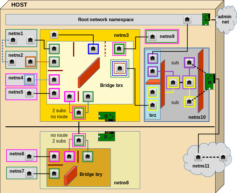
In this article we shall cover experiment 1 and experiment 2 discussed in the last article – i.e. we start with the upper left corner of the drawing.

Experiment 1: Connect two network namespaces directly

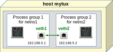
This experiments creates the dotted line between netns1 and netns2. Though simple this experiments lays a foundation for all other experiments.

We place the two different Ethernet interfaces of a veth device in the two (unnamed) network namespaces (with hostnames) netns1 and netns2. We assign IP addresses (of the same network class) to the interfaces and check a basic communication between the network namespaces. The situation corresponds to the following simple picture:

What shell commands can be used for achieving this? You may put the following lines in a file for keeping them for further experiments or to create a shell script:

unshare --net --uts /bin/bash &
export pid_netns1=$!
nsenter -t $pid_netns1 -u hostname netns1
unshare --net --uts /bin/bash &
export pid_netns2=$!
nsenter -t $pid_netns2 -u hostname netns2
ip link add veth11 netns $pid_netns1 type veth peer name veth22 netns $pid_netns2   
nsenter -t $pid_netns1 -u -n /bin/bash
ip addr add 192.168.5.1/24 brd 192.168.5.255 dev veth11
ip link set veth11 up
ip link set lo up
ip a s
exit
nsenter -t $pid_netns2 -u -n /bin/bash
ip addr add 192.168.5.2/24 brd 192.168.5.255 dev veth22
ip link set veth22 up
ip a s
exit
lsns -t net -t uts

If you copy these lines to the prompt of a root shell of some host “mytux” you will get something like the following:

mytux:~ # unshare --net --uts /bin/bash &
[2] 32146
mytux:~ # export pid_netns1=$!

[2]+  Stopped                 unshare --net --uts /bin/bash
mytux:~ # nsenter -t $pid_netns1 -u hostname netns1
mytux:~ # unshare --net --uts /bin/bash &
[3] 32154
mytux:~ # export pid_netns2=$!

[3]+  Stopped                 unshare --net --uts /bin/bash
mytux:~ # nsenter -t $pid_netns2 -u hostname netns2
mytux:~ # ip link add veth11 netns $pid_netns1 type veth peer name veth22 netns $pid_netns2   
mytux:~ # nsenter -t 
$pid_netns1 -u -n /bin/bash
netns1:~ # ip addr add 192.168.5.1/24 brd 192.168.5.255 dev veth11
netns1:~ # ip link set veth11 up
netns1:~ # ip link set lo up
netns1:~ # ip a s
1: lo: <LOOPBACK,UP,LOWER_UP> mtu 65536 qdisc noqueue state UNKNOWN group default qlen 1   
    link/loopback 00:00:00:00:00:00 brd 00:00:00:00:00:00
    inet 127.0.0.1/8 scope host lo
       valid_lft forever preferred_lft forever
    inet6 ::1/128 scope host 
       valid_lft forever preferred_lft forever
2: veth11: <NO-CARRIER,BROADCAST,MULTICAST,UP> mtu 1500 qdisc noqueue state DOWN group default qlen 1000     
    link/ether da:34:49:a6:18:ce brd ff:ff:ff:ff:ff:ff link-netnsid 0
    inet 192.168.5.1/24 brd 192.168.5.255 scope global veth11
       valid_lft forever preferred_lft forever
netns1:~ # exit
exit
mytux:~ # nsenter -t $pid_netns2 -u -n /bin/bash
netns2:~ # ip addr add 192.168.5.2/24 brd 192.168.5.255 dev veth22
netns2:~ # ip link set veth22 up
netns2:~ # ip a s
1: lo: <LOOPBACK> mtu 65536 qdisc noop state DOWN group default qlen 1
    link/loopback 00:00:00:00:00:00 brd 00:00:00:00:00:00
2: veth22: <NO-CARRIER,BROADCAST,MULTICAST,UP,LOWER_UP> mtu 1500 qdisc noqueue state DOWN group default qlen 1000   
    link/ether f2:ee:52:f9:92:40 brd ff:ff:ff:ff:ff:ff link-netnsid 0
    inet 192.168.5.2/24 brd 192.168.5.255 scope global veth22
       valid_lft forever preferred_lft forever
    inet6 fe80::f0ee:52ff:fef9:9240/64 scope link tentative 
       valid_lft forever preferred_lft forever
netns2:~ # exit
exit
mytux:~ # lsns -t net -t uts
        NS TYPE NPROCS   PID USER  COMMAND
4026531838 uts     387     1 root  /usr/lib/systemd/systemd --switched
4026531963 net     385     1 root  /usr/lib/systemd/systemd --switched
4026532178 net       1   581 root  /usr/sbin/haveged -w 1024 -v 0 -F
4026540861 net       1  4138 rtkit /usr/lib/rtkit/rtkit-daemon
4026540984 uts       1 32146 root  /bin/bash
4026540986 net       1 32146 root  /bin/bash
4026541078 uts       1 32154 root  /bin/bash
4026541080 net       1 32154 root  /bin/bash
mytux:~ # 

Of course, you recognize some of the commands from my first blog post. Still, some details are worth a comment:

Unshare, background shells and shell variables

We create a separate network (and uts) namespace with the “unshare” command and background processes.

unshare –net –uts /bin/bash &

Note the options! We export shell variables with the PIDs of the started background processes [$!] to have these PIDs available in subshells later on. Note: From our original terminal window (in my case a KDE “konsole” window) we can always open a subshell window with:

mytux:~ # konsole &>/dev/null   

You may use another terminal window command on your system. The output redirection is done only to avoid KDE message clattering. In the subshell you may enter a previously created network namespace netnsX by

nsenter -t $pid_netnsX -u -n /bin/bash

Hostnames to distinguish namespaces at the shell prompt

Assignment of hostnames to the background processes via commands like

nsenter -t $pid_netns1 -u hostname netns1

This works through the a separation of the uts namespace. See the first post for an explanation.

Create veth devices with the “ip” command

The key command to create a veth device and to assign its two interfaces to 2 different network namespaces is:

ip link add veth11 netns $pid_netns1 type veth peer name veth22 netns $pid_netns2

Note, that we can use PIDs to identify the target network namespaces! Explicit names of the network namespaces are not required!

The importance of a running lo-device in each network namespace

We intentionally did not set the loopback device “lo” up in netns2. This leads to an interesting observation, which many admins are not aware of:

The lo device is required (in UP status) to be able to ping network interfaces (here e.g. veth11) in the local namespace!

This is standard: If you do not specify the interface to ping from via an option “-I” the ping command will use device lo as a default! The ping traffic runs through it! Normally, we just do not realize this point, because lo almost always is UP on a standard system (in its root namespace).

For testing the role of “lo” we now open a separate terminal window:

mytux:~ # konsole &>/dev/null 

There:

mytux:~ # nsenter -t $pid_netns2 -u -n /bin/bash
netns2:~ # ping 192.168.5.2
PING 192.168.5.2 (192.168.5.2) 56(84) bytes of data.
^C
--- 192.168.5.2 ping statistics ---
2 packets transmitted, 0 received, 100% packet loss, time 1008ms   

netns2:~ # ip link set lo up
netns2:~ # ping 192.168.5.2 -c2
PING 192.168.5.2 (192.168.5.2) 56(84) bytes of data.
64 bytes from 192.168.5.2: icmp_seq=1 ttl=64 time=0.017 ms
64 bytes from 192.168.5.2: icmp_seq=2 ttl=64 time=0.033 ms

--- 192.168.5.2 ping statistics ---
2 packets transmitted, 2 received, 0% packet loss, time 998ms    
rtt min/avg/max/mdev = 0.017/0.034 ms

And: Within the same namespace and “lo” down you cannot even ping the second Ethernet interface of a veth device from the first interface – even if they belong to the same network class!

Open a new sub shell and enter e.g. netns1 there:

netns1:~ # ip link add vethx type veth peer name vethy 
netns1:~ # ip addr add 192.168.20.1/24 brd 192.168.20.255 dev vethx    
netns1:~ # ip addr add 192.168.20.2/24 brd 192.168.20.255 dev vethy    
netns1:~ # ip link set vethx up
netns1:~ # ip link set vethy up
netns1:~ # ping 192.168.20.2 -I 192.168.20.1
PING 192.168.20.2 (192.168.20.2) from 192.168.20.1 : 56(84) bytes of data.    
^C
--- 192.168.20.2 ping statistics ---
4 packets transmitted, 0 received, 100% packet loss, time 3000ms
netns1:~ # ip link set lo up
netns1:~ # ping 192.168.20.2 -I 192.168.20.1       
PING 192.168.20.2 (192.168.20.2) from 192.168.20.1 : 56(84) bytes of data.   
64 bytes from 192.168.20.2: icmp_seq=1 ttl=64 time=0.019 ms     
64 bytes from 192.168.20.2: icmp_seq=2 ttl=64 time=0.052 ms                                
^C                                                              
--- 192.168.20.2 ping statistics ---                            
2 packets transmitted, 2 received, 0% packet loss, time 999ms   
rtt min/avg/max/mdev = 0.019/0.035/0.052/0.017 ms               
netns1:~ #                                           

Connection test

Now back to our experiment. Let us now try to ping netns1 from netns2:

netns2:~ # ip a s
1: lo: <LOOPBACK,UP,LOWER_UP> mtu 65536 qdisc noqueue state UNKNOWN group default qlen 1   
    link/loopback 00:00:00:00:00:00 brd 00:00:00:00:00:00
    inet 127.0.0.1/8 scope host lo
       valid_lft forever preferred_lft forever
    inet6 ::1/128 scope host 
       valid_lft forever preferred_lft forever
2: veth22: <BROADCAST,MULTICAST,UP,LOWER_UP> mtu 1500 qdisc noqueue state UP group default qlen 1000     
    link/ether f2:ee:52:f9:92:40 brd ff:ff:ff:ff:ff:ff link-netnsid 0
    inet 192.168.5.2/24 brd 192.168.5.255 scope global veth22
       valid_lft forever preferred_lft forever
    inet6 fe80::f0ee:52ff:fef9:9240/64 scope link 
       valid_lft forever preferred_lft forever
netns2:~ # ping 192.168.5.1
PING 192.168.5.1 (192.168.5.1) 56(84) bytes of data.
64 bytes from 192.168.5.1: icmp_seq=1 ttl=64 time=0.030 ms  
64 bytes from 192.168.5.1: icmp_seq=2 ttl=64 time=0.033 ms  
64 bytes from 192.168.5.1: icmp_seq=3 ttl=64 time=0.036 ms  
^C
--- 192.168.5.1 ping statistics ---                                                                  
3 packets transmitted, 3 received, 0% packet loss, time 1998ms                                       
rtt min/avg/max/mdev = 0.030/0.033/0.036/0.002 ms                                                    
netns2:~ #     

OK! And vice versa:

mytux:~ #  nsenter -t $pid_netns1 -u -n /bin/bash
netns1:~ #  nsenter -t $pid_netns2 -u -n /bin/bash
netns1:~ # ping 192.168.5.2 -c2
PING 192.168.5.2 (192.168.5.2) 56(84) bytes of data.
64 bytes from 192.168.5.2: icmp_seq=1 ttl=64 time=0.023 ms   
64 bytes from 192.168.5.2: icmp_seq=2 ttl=64 time=0.023 ms

--- 192.168.5.2 ping statistics ---
2 packets transmitted, 2 received, 0% packet loss, time 1003ms   
rtt min/avg/max/mdev = 0.023/0.023/0.023/0.000 ms
netns1:~ # 

Our direct communication via veth works as expected! Network packets are not stopped by network namespace borders – this would not make much sense.

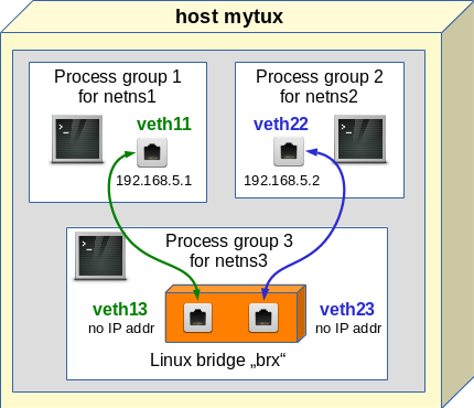
Experiment 2: Connect two namespaces via a bridge in a third namespace

We now try a connection of netns1 and netns2 via a Linux bridgebrx“, which we place in a third namespace netns3:

Note:

This is a standard way to connect containers on a host!

LXC tools as well as libvirt/virt-manager would help you to establish such a bridge! However, the bridge would normally be place inside the host’s root namespace. In my opinion this is not a good idea:

A separate 3rd namespace gets the the bridge and related firewall and VLAN rules outside the control of the containers. But a separate namespace also helps to isolate the host against any communication (and possible attacks) coming from the containers!

So, let us close our sub terminals from the first experiment and kill the background shells:

mytux:~ # kill -9 32146
[2]-  Killed                  unshare --net --uts /bin/bash
mytux:~ # kill -9 32154
[3]+  Killed                  unshare --net --uts /bin/bash

We adapt our setup commands now to create netns3 and bridge “brx” there by using “brctl bradd“. Futhermore we add two different veth devices; each with one interface in netns3. We attach the interface to the bridge via “brctl addif“:

unshare --net --uts /bin/bash &
export pid_netns1=$!
nsenter -t $pid_netns1 -u hostname netns1
unshare --net --uts /bin/bash &
export pid_netns2=$!
nsenter -t $pid_netns2 -u hostname netns2
unshare --net --uts /bin/bash &
export pid_netns3=$!
nsenter -t $pid_netns3 -u hostname netns3
nsenter -t $pid_netns3 -u -n /bin/bash
brctl addbr brx  
ip link set brx up
exit 
ip link add veth11 netns $pid_netns1 type veth peer name veth13 netns $pid_netns3     
ip link add veth22 netns $pid_netns2 type veth peer name veth23 netns $pid_netns3    
nsenter -t $pid_netns1 -u -n /bin/bash
ip addr add 192.168.5.1/24 brd 192.
168.5.255 dev veth11
ip link set veth11 up
ip link set lo up
ip a s
exit
nsenter -t $pid_netns2 -u -n /bin/bash
ip addr add 192.168.5.2/24 brd 192.168.5.255 dev veth22
ip link set veth22 up
ip a s
exit
nsenter -t $pid_netns3 -u -n /bin/bash
ip link set veth13 up
ip link set veth23 up
brctl addif brx veth13
brctl addif brx veth23
exit

It is not necessary to show the reaction of the shell to these commands. But note the following:

  • The bridge has to be set into an UP status.
  • The veth interfaces located in netns3 do not get an IP address. Actually, a veth interface plays a different role on a bridge than in normal surroundings.
  • The bridge itself does not get an IP address.

Bridge ports

By attaching the veth interfaces to the bridge we create a “port” on the bridge, which corresponds to some complicated structures (handled by the kernel) for dealing with Ethernet packets crossing the port. You can imagine the situation as if e.g. the veth interface veth13 corresponds to the RJ45 end of a cable which is plugged into the port. Ethernet packets are taken at the plug, get modified sometimes and then are transferred across the port to the inside of the bridge.

However, when we assign an Ethernet address to the other interface, e.g. veth11 in netns1, then the veth “cable” ends in a full Ethernet device, which accepts network commands as “ping” or “nc”.

No IP address for the bridge itself!
We do NOT assign an IP address to the bridge itself; this is a bit in contrast to what e.g. happens when you set up a bridge for networking with the tools of virt-manager. Or what e.g. Opensuse does, when you setup a KVM virtualization host with YaST. In all these cases something like

ip addr add 192.168.5.100/24 brd 192.168.5.255 dev brx 

happens in the background. However, I do not like this kind of implicit politics, because it opens ways into the namespace surrounding the bridge! And it is easy to forget this bridge interface both in VLAN and firewall rules.

Almost always, there is no necessity to provide an IP address to the bridge itself. If we need an interface of a namespace, a container or the host to a Linux bridge we can always use a veth device. This leads to a much is much clearer situation; you see the Ethernet interface and the port to the bridge explicitly – thus you have much better control, especially with respect to firewall rules.

Enter network namespace netns3

Now we open a terminal as a sub shell (as we did in the previous example) and enter netns3 to have a look at the interfaces and the bridge.

mytux:~ # nsenter -t $pid_netns3 -u -n /bin/bash
netns3:~ # brctl show brx
bridge name     bridge id               STP enabled     interfaces
brx             8000.000000000000       no
netns3:~ # ip a s
1: lo: <LOOPBACK> mtu 65536 qdisc noop state DOWN group default qlen 1
    link/loopback 00:00:00:00:00:00 brd 00:00:00:00:00:00
2: brx: <BROADCAST,MULTICAST,UP,LOWER_UP> mtu 1500 qdisc noqueue state UP group default qlen 1000
    link/ether ce:fa:74:92:b5:00 brd ff:ff:ff:ff:ff:ff
    inet6 fe80::1c08:76ff:fe0c:7dfe/64 scope link 
       valid_lft forever preferred_lft forever
3: veth13@if2: <BROADCAST,MULTICAST,UP,LOWER_UP> mtu 1500 qdisc noqueue master brx state UP group default qlen 1000   
    link/ether ce:fa:74:92:b5:00 brd ff:ff:ff:ff:ff:ff link-netnsid 0
    inet6 fe80::ccfa:74ff:fe92:b500/64 scope link 
       valid_lft forever preferred_lft forever
4: veth23@if2: <BROADCAST,MULTICAST,UP,LOWER_UP> mtu 1500 qdisc noqueue master brx state UP group default qlen 1000   
    link/ether fe:5e:0b:d1:44:69 brd ff:ff:ff:ff:ff:ff link-netnsid 1
    inet6 fe80::fc5e:
bff:fed1:4469/64 scope link 
       valid_lft forever preferred_lft forever
netns3:~ # bridge link
3: veth13 state UP @brx: <BROADCAST,MULTICAST,UP,LOWER_UP> mtu 1500 master brx state forwarding priority 32 cost 2    
4: veth23 state UP @brx: <BROADCAST,MULTICAST,UP,LOWER_UP> mtu 1500 master brx state forwarding priority 32 cost 2    

Useful commands

Let us briefly discuss some useful commands:

Incomplete information of “brctl show”
Unfortunately, the standard command

brctl show brx

does not work properly inside network namespaces; it does not produce a complete output. E.g., the attached interfaces are not shown. However, the command

ip a s

shows all interfaces and their respective “master“. The same is true for the very useful “bridge” command :

bridge link

If you want to see even more details on interfaces use

ip -d a s

and grep the line for a specific interface.

Just for completeness: To create a bridge and add a veth devices to the bridge, we could also have used:

ip link add name brx type bridge
ip link set brx up
ip link set dev veth13 master brx   
ip link set dev veth23 master brx   

Connectivity test with ping
Now, let us turn to netns1 and test connectivity:

mytux:~ # nsenter -t $pid_netns1 -u -n /bin/bash
netns1:~ # ip a s 
1: lo: <LOOPBACK,UP,LOWER_UP> mtu 65536 qdisc noqueue state UNKNOWN group default qlen 1
    link/loopback 00:00:00:00:00:00 brd 00:00:00:00:00:00
    inet 127.0.0.1/8 scope host lo
       valid_lft forever preferred_lft forever
    inet6 ::1/128 scope host 
       valid_lft forever preferred_lft forever
2: veth11@if3: <BROADCAST,MULTICAST,UP,LOWER_UP> mtu 1500 qdisc noqueue state UP group default qlen 1000    
    link/ether 6a:4d:0c:30:12:04 brd ff:ff:ff:ff:ff:ff link-netnsid 0
    inet 192.168.5.1/24 brd 192.168.5.255 scope global veth11
       valid_lft forever preferred_lft forever                                                       
    inet6 fe80::684d:cff:fe30:1204/64 scope link                                                     
       valid_lft forever preferred_lft forever                                                       
netns1:~ # ping 192.168.5.2
PING 192.168.5.2 (192.168.5.2) 56(84) bytes of data.
64 bytes from 192.168.5.2: icmp_seq=1 ttl=64 time=0.039 ms
64 bytes from 192.168.5.2: icmp_seq=2 ttl=64 time=0.045 ms
64 bytes from 192.168.5.2: icmp_seq=3 ttl=64 time=0.054 ms
^C
--- 192.168.5.2 ping statistics ---
3 packets transmitted, 3 received, 0% packet loss, time 1998ms
rtt min/avg/max/mdev = 0.039/0.046/0.054/0.006 ms
netns1:~ # nc -l 41234

Note that – as expected – we do not see anything of the bridge and its interfaces in netns1! Note that the bridge basically is a device on the data link layer, i.e. OSI layer 2. In the current configuration we did nothing to stop the propagation of Ethernet packets on this layer – this will change in further experiments.

Connectivity test with netcat
At the end of our test we used the netcat command “nc” to listen on a TCP port 41234. At another (sub) terminal we can now start a TCP communication from netns2 to the TCP port 41234 in netns1:

mytux:~ # nsenter -t $pid_netns2 -u -n /bin/bash
netns2:~ # nc 192.168.5.1 41234
alpha
beta

This leads to an output after the last command in netns1:

netns1:~ # nc -l 41234
alpha
beta

So, we have full connectivity – not only for ICMP packets, but also for TCP packets. In yet another terminal:

mytux:~ # nsenter -t $pid_netns1 -u -n /bin/bash
netns1:~ # netstat -a
Active 
Internet connections (servers and established)
Proto Recv-Q Send-Q Local Address           Foreign Address         State      
tcp        0      0 *:41234                 *:*                     LISTEN      
tcp        0      0 192.168.5.1:41234       192.168.5.2:45122       ESTABLISHED     
Active UNIX domain sockets (servers and established)
Proto RefCnt Flags       Type       State         I-Node Path   
netns1:~ # 

Conclusion

It is pretty easy to connect network namespaces with veth devices. The interfaces can be assigned to different network namespaces by using a variant of the “ip” command. The target network namespaces can be identified by PIDs of their basic processes. We can link to namespaces directly via the interfaces of one veth device.

An alternative is to use a Linux bridge (for Layer 2 transport) in yet another namespace. The third namespace provides better isolation; the bridge is out of the view and control of the other namespaces.

We have seen that the commands “ip a s” and “bridge link” are useful to get information about the association of bridges and their assigned interfaces/ports in network namespaces.

In the coming article
Fun with veth-devices, Linux bridges and VLANs in unnamed Linux network namespaces – IV
we extend our efforts to creating VLANs with the help of our Linux bridge. Stay tuned ….