During previous posts of our excursion on network namespaces, veth-devices and virtual networking
- Fun with … – III [Connecting network namespaces (or containers) by veth devices and virtual Linux bridges],
- Fun with … – IV [Virtual VLANs for network namespaces (or containers) and rules for VLAN tagging at Linux bridge ports],
- Fun with …. – V [Creation of two virtual VLANs for 2 groups of network namespaces/containers by configuring a Linux bridge]
- Fun with …. – VI [Connection of two Linux bridges each with 2 VLANs]
we have studied virtual VLANs a bit. We saw that virtual VLANs can be defined just by applying certain configuration options to Linux bridge ports. In addition, virtual VLANs can be extended over several Linux bridges via veth sub-interfaces OR pure veth trunk connections.
These possibilities support already a large variety of options for the configuration of virtual networks (e.g. for a bunch of containers). We discussed some simple illustrative test cases, in which containers were represented by simple network namespaces.
However, so far, four properties characterized our test configurations:
- All network namespaces (or container hosts) connected to a Linux bridge belonged to exactly one of the involved VLANs.
- All network namespaces (or container hosts) belonging to the involved VLANs were connected to a Linux bridge via ports which sent out untagged packets from the bridge to the target namespaces and received untagged packets from the namespaces (or container hosts).
- The VLANs (e.g. VLAN1, VLAN2) were completely defined by PVID/VID definition at Linux bridge ports, only. We eliminated in addition default PVID/VID values. Thus, the VLANs were completely isolated from each other: No host/namespace of a VLAN1 could communicate with a host/namespace belonging to a different VLAN2.
- Different Linux bridges (which could reside on different hosts) were connected by (virtual or real) cables between trunk ports or sub-interface ports; the cables connecting the bridges transferred packets with different tags. We used this to keep up the isolation of the VLANs against each other even when we extended the VLANs over multiple bridges.
The third point may be good in the sense of security in many applications – but it is also restrictive. The first deficit may be that at least some hosts in a VLAN2 should be able to reach a certain server in VLAN1. This problem can be solved by establishing routing, forwarding and packet filtering outside the bridge. But there may be other requirements ….
New challenges
More interesting may be configurations
- where you need to set up some containers/namespaces as common members of two ore more VLANs
- or in which you need to establish network namespaces for gathering network packets
from different VLANs and organize a common communication with further networks via specific interfaces.
In future posts of this series, we, therefore, introduce additional network namespaces (representing LXC or Docker containers) to test examples for such configurations. These new namespaces should at least be able to communicate with member namespaces/hosts of different VLANs and transfer packets from multiple VLANs to other network namespaces or routers.
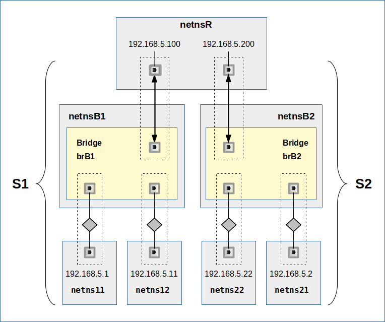
In the present post I walk through some basic considerations of such configurations. For this purpose we restrict the number of involved VLANs to 2 (VLAN1: green tags / VLAN2: pink tags). Each VLAN shall be represented by one example member network namespace (VLAN1: netns1 / VLAN2: netns2). In addition, we introduce a third network namespace netns3, which shall be connected to the VLANs and which should fulfill the following requirements:
- Requirement 1: netns3 shall be able to receive packets from members of both VLANs and send packets to destination targets in both VLANs. I.e., netns3 must be able to communicate with member systems of both VLANs.
- Requirement 2: netns3 shall, however, not become a packet forwarder between the VLANs; the VLANs shall remain separated despite the fact that they have a common communication partner netns3.
After all we have learned in this article series, we would, of course, try to establish the connection between members of VLAN1 (represented by netns1) and members of VLAN2 (netns2) to netns3 with the help of an intermediate network namespace netnsX. If required we would equip netnsX with a Linux bridge. Thus, the requirements lead to a typical
“3 point connection problem“:
Each of the VLANs is connected to netnX by 2 separate “connectors” (NICs or ports of a Linux bridge inside netnsX). A third “connector” attaches netns3 somehow. Schematically this is shown in the following graphics:
We associate VLAN1 with VLAN packet tags depicted in green color, VLAN2 with packets tags in pink. From “requirement 2” we conclude that we have to be careful with forwarding inside of BOTH netns3 AND netnsX.
Note:
We are not talking about reaching a member of VLAN2 from certain members of VLAN1. We shall touch this VLAN subject, too, but only as a side aspect. In the center of our analysis are instead network namespaces which can talk freely to members of two VLANs and which can receive and work with packets from two VLANs without destroying the communication isolation of members in VLAN1 against members in VLAN2.
What are real world applications for scenarios with network namespaces connected to two or more VLANs?
Two basic applications scenarios are the following:
- A common administrative network namespace – or container host – for systems in both VLANs. This namespace/container shall operate without allowing for traffic between the VLANs.
- A system which transfers packets from/to systems in both VLANs via a router to/from the external world or the Internet – without allowing for traffic between the VLANs.
The challenge is to find virtual network configurations for such scenarios. To make it a bit more challenging we assume that both VLANs are defined for systems of the same IP network class. (There is no requirement that limits different VLANs to different IP classes. A VLAN can cover several IP class networks; on the other side two different VLANs can each have members of the same IP class).
There are of course more application scenarios – but the two elementary ones named above cover most of the basic principles. We shall see that – depending on the solution approach – routing, packet filters and even forwarding must be addressed to realize the objectives of a certain scenario.
Ambiguities: Two different classes of packet transfer solutions
In netns3 we need to work with packets arriving from both VLANs. We also need to send back packets to destinations in both VLANs. But, there is a basic ambiguity related to the third connector and the connection line between netnsX and netns3. It is expressed by the following question:
Do we want to or can we afford to exchange tagged packets between netnsX and netns3?
This is not so trivial a question as it may seem to be! The answer depends on whether the network devices or applications inside netns3 know how to deal with and how to direct or transfer tagged packets.
In case we keep up VLAN tags until the inside of netns3 we must either provide a proper termination for the connection interface(s) or be able to pass tagged packets onward. If, however, netns3 does not know how to deal with tagged packets or if it makes no sense to keep up tagging we would rather send untagged packets from netnsX to netns3. One good reason why it may not make sense to keep up tagging could be that the tags would not survive a subsequent routing to the outside world anyway.
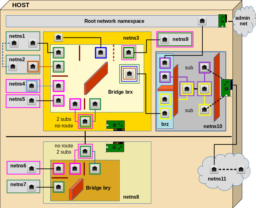
Thus we arrive at two rather different classes of connectivity solutions:
Let us first concentrate on termination solutions for tagged packets inside netns3 as depicted on the left side of the upper drawing:
As we have already seen in previous posts it is no problem to keep up tagging on the way from netns1 or netns2 to netns3. We know how to transfer tagged and untagged packets in and out of Linux bridges and thus we can be confident to find a suitable transfer solution based on a bridge inside netnsX. By the help of 2 sub-interfaces of e.g. a virtual veth device we could terminate the network transport properly inside netns3. So, it seems to be easy to make netns3 a member of both VLANs in this first class of connection approach. But, as we shall understand in a minute, we need a little more than just a bridge in netnsX and veth sub-interfaces to get a working configuration ….
A really different situations arises if we needed a configuration as presented on the right side of the graphics. The challenge there is not so much the creation of untagged packets going out of netnsX but the path of VLAN-ignorant packets coming in e.g. from the external world through netns3 and heading for members of either VLAN. Such packets must somehow then be directed to the right VLAN according to the IP address of the target. Such a targeting problem typically requires some kind of routing. So, on first sight a Linux bridge does not seem to be of much help in netnsX as there is no routing on a level 2 device! But, actually, we shall find that a Linux bridge in netnsX can lead to a working solution for untagged packets from/to netns3 – but such a solution comes with a prize.
Approaches with terminated VLAN connections in a common network namespace fit very well to the scenario of a common container host for the administration of systems in multiple VLANs. Solutions which instead use untagged packets entering and leaving netns3, instead fits very well to scenarios where multiple VLANs want to use a common connection (Ethernet card) or a common router to external networks.
Solutions which use packet tags and terminate VLAN traffic inside a common member of multiple VLANs
Let us assume that netns3 shall represent a host for the administration of netns1 in VLAN 1 (green) and netns2 in VLAN 2 (pink). Let us decide to keep up tagging all along the way from netns1 or netns2 to netns3. From the previous examples in this blog post series the following approaches for a netnsX-bridge-configuration look very plausible:
However, if you only configured the bridge, its ports and the veth devices properly and eventually tried pinging from netns1 to netns3 you would fail. (There are articles and questions on the Internet describing problems with such situations…). So, what is missing? The answer is as simple as it is instructive:
netns3 needs defined well routes to IPs residing in netns1 or netns2! Such routes would be different regarding the device to use for reaching IPs in netns1 in comparison to the device of routes leading to the IPs residing in netns2.
The requirement of defined routes in netns3 with multiple VLAN sub-devices
VLANs define a closed broadcast environment on TCP/IP network level 2. Why are broadcasts so important? Because we need a working ARP protocol to connect network layer 2 to layer 3. And ARP sends broadcast requests for the MAC address of a target, which has a given IP address AND which, hopefully, is a member of the same VLAN.
With a proper bridge port configuration an ARP request packet would travel all along from netns1 to netns3. But further? And what about ARP answer packets from netns3 itself? And what about ARP requests from netns3 regarding target IPs in either VLAN?
In netns3 we have just one IP for the veth end-point, but two related sub-devices … From the perspective of netns3 this makes the situation regarding the path (back) from netns3 to netns1 or netns2.
The situation of netns3 is a bit compatible with a host having two distinct NICs for different LAN segments. Even if proper routes were defined, only activated forwarding between the LAN segments attached to the router would allow packets to move from one segment to the other. However, in our situation, we would never activate forwarding in netns3 as we want to keep the VLANs separated. So, we assume that we have no problem with VLAN separation …
In addition VLANs mark separated areas of Ethernet broadcasts. After some recapitulation of ARP basics and the fact that ARP uses Ethernet broadcast packets for ARP requests we would assume that such packets will NOT move from one segment (here: VLAN with green tags) via netns3 into our second attached segment (here: VLAN with pink tags). Tagging would in addition surely prevent such a transfer.
This leads to the conclusion that ARP requests originating e.g. in netns1 would just reach netns3. But will they be answered if the request was for the IP of the veth end-point residing in netns3?
The big problem is that any answer will only be transported to the requesting namespace if the respective unicast packet gets the right tagging. But how should netns3 know which way to send the answer? Meaning: By what criterion should netns3 know which of the sub-devices to use to create a proper ARP reply packet? It cannot get the answer from an IP netmask – we have two sub-devices for one and the same IP!
Well an answer could be sent along the correct path if netns3 knew which IPs reside behind which of the two available veth sub-devices. This is exactly what defined routes in routing tables are good for!
This line of thought leads us to the suspicion that ARP requests coming from netns1 or netns3 either remain unanswered or that a reply requires defined routes. Also for sending an ARP request from netns3 to an IP in netns1, netns3 needs to know which veth-subdevice to use. I.e. netns3 definitively must know which IPs are located behind with veth-subdevice!
But (independent of ARP) the real challenge is the way back of ICMP answering packets from netns3 to netns2 or netns1. Such answering packets must reach their targets before we can be sure that any other communication on levels 3 and 4 will work properly between netns1 and netns3 or between netns2 and netns3. You should not forget that our namespaces in real world virtualization scenarios would represent Linux hosts and respective networking programs. But how can netns3 (or a respective host program) know where to direct ICMP answering packets to if and when there are two possible paths and devices avalable Without help it can not. Reason again: The IP network mask does not help!
So, the proper answer to our problems is:
We need to establish routes inside netns3 when we
(1) want to keep up the separation of the VLANs up until to 2 different termination points inside netns3 (for one IP),
(2) but nevertheless want to include netns3-based packets in the direction of netns1 OR netns2 in the communication.
The routes for packets going out from netns3 to either netns1 or netns2 must assign IP-targets located in each of the VLANs to one of the 2 network interfaces (termination points) inside netns3 in a unique way.
Note in addition:
Whenever the different VLANs have members with an IP of one and the same IP class, then you may have to differentiate routes in the sense of a “host IP <=> NIC-interface” relation, instead of the usual relation “network class <=> interface”. Often enough people forget this specific type of routing …
Regarding our special situation such routes must be defined for all members of each VLAN. I shall give examples for corresponding commands in my next blog post of this series.
I am not going to clarify open ARP-related questions which arise for netns3 in this post. One should not forget regarding ARP that PROXY ARP could be activated in netns3. This increases complexity. I am going to investigate the behavior of ARP packets in more detail for namespaces in a routing position between LAN segments via respective experiments in some other posts. For first insights see e.g.
More fun with veth, network namespaces, VLANs – III – L2-segments of the same IP-subnet and routes in coupling network namespaces
More fun with veth, network namespaces, VLANs – IV – L2-segments, same IP-subnet, ARP and routes
Forwarding?
As we talk of routing: Do we need forwarding, too? Answer: No, not as long as netns3 is the final target or the origin of packet transport in a given application scenario. Why is this important? Because routing between interfaces connected to bridge ports of different VLANs would establish a communication connection between otherwise separated VLANs.
To enable packets to cross VLAN borders we either have to destroy the separation already on a bridge port level OR we must allow for routing and forwarding between NICs which are located outside the bridge but which are connected to ports of the bridge. E.g., let us assume that the sub-interfaces in netns3 are named veth33.10 (VLAN1 termination) and veth33.20 (VLAN2 termination). If we had not just set up routes like
route add 192.168.5.1 veth33.10
route add 192.168.5.4 veth33.20
but in addition had enabled forwarding with
echo 1 > /proc/sys/net/ipv4/conf/all/forwarding
inside netns3 we would have established a communication line between our two VLANs. Fortunately, in many cases, forwarding is not required in a common member of two VLANs. Most often only route definitions are necessary. In particular, we can set up a host which must perform administrative tasks in both VLANs without creating an open communication line between the VLANs. However, we would have to trust the administrator of netns3 not to enable forwarding. Personally, I would not rely on this; it is more secure to establish port and IP related packet filtering on the bridge inside netnsX. Especially rules in the sense:
Only packets for a certain IP address are allowed to leave the Linux bridge (which establishes the VLANs) across a certain egress port to a certain VLAN member.
Such rules for bridge ports can be set up e-g- with special iptables commands for bridged packets.
Intermediate conclusions for solutions with VLAN termination in a common network namespace
We summarize the results of our theoretical discussion for the first class of solutions:
- VLAN termination inside a network namespace (or container host), which shall become a common member of several VLANs, can easily be achieved with sub-interfaces of a veth device. The other interface of the veth pair can be attached by sub-interfaces OR as a pure trunk port to a Linux bridge which is connected to the different VLANs or which establishes the VLANs itself by proper port configurations.
- If we terminate VLANs inside a network namespace or container host, which shall become a member of two or more VLANs, then we need to define proper routes to IP targets behind each of the different VLAN related interfaces. However, we do NOT need to enable forwarding in this namespace or container host.
A three point netnX solution without packet tagging, but with forwarding to a common target network namespace
Now, let us consider solutions of the second class indicated above. If you think about it a bit you may come up with the following basic and simple approach regarding netnsX and netns3:
This solution is solid in the sense that it works on network level 3 and that it makes use of standard routing and forwarding. The required VLAN tagging at each of the lower connection points in netnsX can be achieved by a properly configured sub-interface of a veth device interface. We do not employ any bridge services in netnsX in this approach; packet distribution to VLAN members must be handled in other network namespaces behind the VLAN connection points in netnsX. (We know already how to do this …).
This simple solution, however, has its prize:
We need to enable forwarding for the transfer of packets from the VLAN connection interfaces (attaching e.g. netns1 and netns2 to netnsX) to the the interface attaching netns3 to netnsX. But, unfortunately, this creates a communication line between VLAN1 and VLAN2, too! To compensate for this we must set up a packet filter, with rules disallowing packets to travel between the VLAN connection points inside netnsX. Furthermore, packets coming via/from netns3 shall only be allowed to pass through exactly one of the lower VLAN interfaces in netnsX if and when the target IP fits to a membership in the VLAN behind the NIC.
There is, by the way a second prize, we have to pay in such a router like solution for the connection of VLANs to an outside world without tags:
Level 3 routing costs a bit more computational time than packet transport on level 2.
But, if you (for whatever reason) only can provide one working Ethernet interface to the outside world, it is a small prize to pay!
Intermediate result:
An intermediate virtual network namespace (or virtual host) netnsX with conventional routing/forwarding AND appropriate packet filter rules on a firewall can be used to control the communication of members of two or more VLANs to the outside world via a third (common) interface attached to netnsX. We do not need to care for VLAN tags beyond this third interface as VLAN tags do not survive forwarding. Further routing, forwarding and required NAT configurations with respect to the Internet can afterward be done inside yet another virtual namespace “netns3” (with a bridge and an attached real Ethernet card) or even beyond netns3 in an external physical router.
A three point netnX solution without packet tagging – but based on a Linux bridge
Now, let us consider how a Linux bridge in netnsX could transfer packets even if we do not tag packets on their way between the bridge and netns3. I.e., if we want connect two VLANs to a VLAN-ignorant network namespace netns3 and a VLAN indifferent world beyond netns3. What is the problem with a configuration as indicated on the right side of the picture on different solution classes?
A port to netns3 which shall emit untagged packets from a VLAN-aware Linux bridge must be configured such
- that it accepts tagged packets from both VLAN1 and VLAN2 on egress; i.e. we must apply two VID settings (for green and pink tagged pakets).
- that it sends out packets on egress untagged; i.e. we must configure the port with the flag “untagged”.
But VID settings also filter and drop incoming “ingress” packets at a port! E.g. untagged packets from netns3 are dropped on their way into the Linux bridge. See the post Fun with … – IV for related rules on Linux bridge ports. This is a major problem:
Firstly, because we cannot send any ARP broadcast requests from netns3 to netns1 or netns2. And, equally bad, netns3 cannot answer to any ARP requests which it may receive from members of VLAN1 or VLAN2:
ARP broadcast requests from e.g. netns1 will pass the bridge port to netns3 and arrive there untagged. However, untagged ARP answer packets will not be allowed to enter the bridge at the port for netns3 because they do not fit to the VID settings at this port.
But, can’t we use PVID settings? Hmm, remember: Only one PVID setting is allowed at a port! But in our case ARP broadcast and answering packets must be able to reach members of both VLANs! Are we stuck, then? No, a working solution is the following:
In the drawing above we have indicated PVID settings by squares with dotted, colored borders and VID settings by squares with solid borders. The configuration may look strange, but it eliminates the obstacles for ARP packet exchange! And it allows for packet transfer from netns3 to both VLANs.
Actually, the “blue” PVID/VID setting reflects the default PVID/VID settings (VID=1; PVID=1) which come up whenever we create a port in VLAN-aware bridge! Up to now, we have always deleted these default values to guarantee a complete VLAN isolation; but you may already have wondered why this default setting takes place at all. Now, you got a reason.
If you, in addition, take into account that a Linux bridge learns about port-MAC relations and that it – under normal conditions – forwards or filters packets during bridge internal forwarding between ports
- according to MAC addresses located behind a port
- AND tags matching VID values at a port,
you may rightfully assume that packets cannot move from VLAN1 to VLAN2 or vice versa under normal operation conditions. We shall test this in an example scenario in one of the coming blog posts.
HOWEVER ….virtual networks with level 2 bridges are endangered areas. The PVID/VID settings of our present bridge based approach weaken the separation between the VLANs significantly.
Security aspects
For all configurations discussed above, we must be careful with netns3: netns3 is in an excellent position to potentially transfer packets between VLAN1 and VLAN2 – either by direct forwarding/routing in some of the above scenarios or by capturing, manipulating and re-directing packets. Secondly, netns3 is in an excellent position for man-in-the-middle-attacks
- regarding traffic between members of either VLAN
- or regarding traffic between the VLANs and the outside world beyond netns3.
netns3 can capture, manipulate and redirect any packets passing it. As administrators we should, therefore, have full control over netns3.
In addition: If you ever worked on defense measures against bridge related attack vectors you know
- that a Linux bridge can be forced into a HUB mode if flooded with wrong or disagreeing MAC information.
- that man-in-the-middle-attacks are possible by flooding hosts attached to bridges with wrong MAC-IP-information; this leads to manipulated ARP tables at the attacked targets.
These points lead to potential risks especially in the last bridge based solution to our three point problem. Reason: The “blue” PVID/VID settings there eliminate the previously strict separation of the two VLANs for packets which come from netns3 and enter the bridge at a related port. We rely completely on correct entries in the bridge’s MAC/port relation table for a safe VLAN separation.
But the bridge could be manipulated from any of the attached container hosts into a HUB mode. This in turn would e.g. allow a member of VLAN1 to see (e.g. answering) packets, which arrive from netns3 (or an origin located beyond netns3) and which are targeted to a member of VLAN2. Such packets may carry enough information for opening other attack vectors.
So, a fundamental conclusion of our discussion is the following:
It is essential that you apply packet filter rules on bridge based solutions that hinder packets to reach targets (containers) with the wrong IP/MAC-relation at egress ports! Such rules can be applied to bridge ports by the various means of Linux netfilter tools.
On a host level this may be a task which becomes relatively difficult if you apply flexible DHCP-based IP assignments to members of the VLANs.
But, if you need to choose between flexibility and full control about which attached namespace/container gets which IP (and MAC) and your virtual networks are not too big : go for control – e.g via setup scripts.
Summary and outlook
Theoretically, there are several possibilities to establish virtual communication lines from a network namespace or container to members of multiple virtual VLANs. Solutions with tagged packet transfer require a proper termination inside the common member namespace and the definition of routes. As long as we do not enable forwarding outside the VLAN establishing Linux bridge the VLANs remain separated. Solutions where packets are transferred untagged from the VLANs to a target network namespace require special PVID/VID settings at the bridge port to enable a bidirectional communication. These settings weaken the VLAN separation and underline the importance of packet filter rules on the Linux bridge and for the various bridge ports.
In the next post of this series
Fun with veth-devices, Linux bridges and VLANs in unnamed Linux network namespaces – VIII
we will look at commands for setting up a test environment for 2 VLANs with a common communication target. And we will test the considerations discussed above.
In the meantime : Happy New Year – and stay tuned for more adventures with Linux, Linux virtual bridges and network namespaces …