Fun with veth-devices, Linux bridges and VLANs in unnamed Linux network namespaces – II

The topics of this blog post series are

  • the basic handling of network namespaces
  • and virtual networking between different network namespaces.

One objective is a better understanding of the mechanisms behind the setup for future (LXC) containers on a host; containers are based on namespaces (see the last post of this series for a mini introduction). The most important Linux namespace for networking is the so called “network namespace”.

As explained in the previous article
Fun with veth-devices, Linux bridges and VLANs in unnamed Linux network namespaces – I
it is interesting and worthwhile to perform network experiments without referring to explicit names for network namespaces. Especially, when you plan to administer LXC containers with libvirt/virt-manager. You then cannot use the standard LXC tools or “ip“-options for explicit network namespace names.

We, therefore, had a look at relevant options for the ip-command and other typical userspace tools. The basic trick was/is to refer to PIDs of the processes originally associated with network namespaces. I discussed commands for listing network namespaces and associated processes. In addition, I showed how one can use shells for entering new or existing unnamed network namespaces. We finalized the first post with the creation of a veth device inside a distinct network namespace.

Advanced experiments – communication scenarios between network namespaces and groups of namespaces (or containers)

Regarding networking a container is represented by a network namespace, associated network devices and rules. A network namespace provides an isolation of the network devices assigned to this namespace plus related packet filter and routing rules from/against other namespaces/containers.

But very often you may have to deal not only with one container on a host but a whole bunch of containers. Therefore, another objective of experiments with network namespaces is

  • to study the setup of network communication lines between different containers – i.e. between different network namespaces –
  • and to study mechanisms for the isolation of the network packet flow between certain containers/namespaces against packets and from communication lines of other containers/namespaces or/and the host.

The second point may appear strange at first sight: Didn’t we learn that the fundamental purpose of (network) namespaces already is isolation? Yes, the isolation of devices, but not the isolation of network packet crossing the network namespace borders. In realistic situations we, in addition, need to establish and at the same time isolate communication paths in between different containers/namespaces and to their environment.

Typically, we have to address a grouping of containers/namespaces in this context:

  • Different containers on one or several hosts should be able to talk to each other and the Internet – but only if these containers are members of a defined group.
  • At the same time we may need to isolate the communication occurring within a group of containers/namespaces against the communication flow of containers/namespaces of another group and against communication lines of the host.
  • Still, we may need to allow namespaces/containers of different groups to use a common NIC to the Internet despite an otherwise isolated operation.

All this requires a confinement of the flow of distinguished network packages along certain paths between network namespaces. Thus, the question comes up how to achieve separated virtual communication circuits between network namespaces already on the L2 level and across possibly involved virtual devices.

Veth devices, VLAN aware Linux bridges (or other types of virtual Linux switches) and VLAN tagging play a key role in simple (virtual) infrastructure approaches to such challenges. Packet filter rules of Linux’ netfilter components additionally support the control of packet flow through such (virtual) infrastructure elements. Note:

The nice thing about network namespaces is that we can study all required basic networking principles easily without setting up LXC containers.

Test scenarios – an overview

I want to outline a collection of interesting scenarios for establishing and isolating communication paths between namespaces/containers. We start with a basic communication line between 2 different network namespaces. By creating more namespaces and veth devices, a VLAN aware bridge and VLAN rules we extend the test scenario’s complexity step by step to cover the questions posed above. See the graphics below.

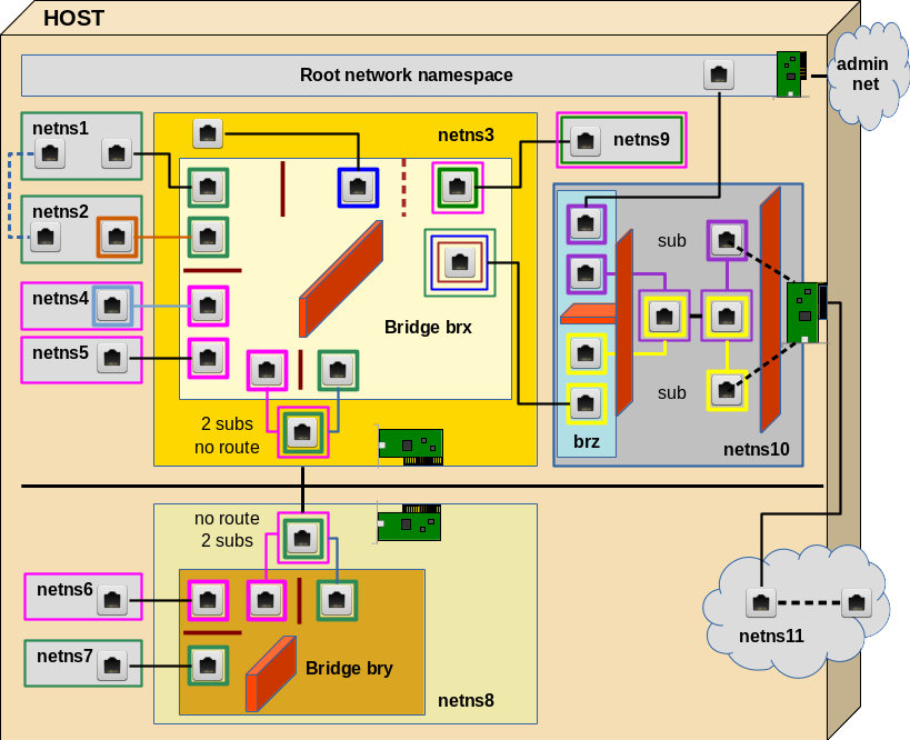
Everything actually happens on one host. But the elements of lower part (below the horizontal black line) also could be placed on a different host. The RJ45 symbols represent Ethernet interfaces of veth devices. These interfaces, therefore, appear mostly in pairs (as long as we do not define sub interfaces). The colors represent IDs (VIDs) of VLANs. Three standard Linux bridges are involved; on each of these bridges we shall activate VLAN filtering. We shall learn that we can, but do not need to tag packets outside of VLAN filtering bridges – with a few interesting exceptions.

I suggest 10 experiments to perform within the drawn virtual network. We cannot discuss details of all experiments in one blog post; but in the coming posts we shall walk through this graphics in several steps from the top to the bottom and from the left to the right. Each step will be accompanied by experiments.

I use the abbreviation “netns” for “network namespace” below. Note in advance that the processes (shells) underlying the creation of network namespaces in our experiments always establish “uts” namespaces, too. Thus we can assign different hostnames to the basic shell processes – this helps us to distinguish in which network namespace shell we operate by just looking at the prompt of a shell. All the “names” as netns1, netns2, … appearing in the examples below actually are hostnames – and not real network namespace names in the sense of “ip” commands or LXC tools.

I should remark that I did the experiments below not just for fun, but because the use of VLAN tags in environments with Linux bridges are discussed in many Internet articles in a way which I find confusing and misleading. This is partially due to the fact that the extensions of the Linux kernel for VLAN definitions with the help of Linux bridges have reached a stable status only with kernel 3.9 (as far as I know). So many articles before 2014 present ideas which do not fit to the present options. Still, even today, you stumble across discussions which claim that you either do VLANs or bridging – but not both – and if, then only with different bridges for different VLANs. I personally think that today the only reason for such approaches would be performance – but not a strict separation of technologies.

Experiments

I hope the following experiments will provide readers some learning effects and also some fun with veth devices and bridges:

Experiment 1: Connect two namespaces directly
First we shall place the two different Ethernet interfaces of a veth device in two different (unnamed) network namespaces (with hostnames) netns1 and netns2. We assign IP addresses (of the same network class) to the interfaces and check a basic communication between the network namespaces. Simple and effective!

Experiment 2: Connect two namespaces via a bridge in a third namespace
Afterwards we instead connect our two different network namespaces netns1 and netns2 via a Linux bridge “brx” in a third namespace netns3. Note: We would use a separate 3rd namespace also in a scenario with containers to get the the bridge and related firewall and VLAN rules outside the control of the containers. In addition such a separate namespace helps to isolate the host against any communication (and possible attacks) coming from the containers.

Experiment 3: Establish isolated groups of containers
We set up two additional network namespaces (netns4, netns5). We check communication between all four namespaces attached to brx. Then we put netns1 and netns2 into a group (“green”) – and netns4 and netns5 into another group (“rosa”). Communication between member namespaces of a group shall be allowed – but not between namespaces of different groups. Despite the fact that all namespaces are part of the same IP address class! We achieve this on the L2 level by assigning VLAN IDs (VIDs) to the bridge ports to which we attach netns1, netns2, em>netns2 and netns5.

We shall see how “PVIDs” are assigned to a specific port for tagging packets that move into the bridge through this port and how we untag outgoing packets at the very same port. Conclusion: So far, no tagging is required outside the Linux bridge brx for building simple virtual VLANs!

Experiment 4: Tagging outside the bridge?
Although not required we repeat the last experiment with defined subinterfaces of two veth devices (used for netns2 and netns5) – just to check that packet tagging occurs correctly outside the bridge. This is done in preparation for other experiments. But for the isolation of VLAN communication paths inside the bridge only the tagging of packets coming into the bridge through a port is relevant: A packet coming from outside is first untagged and then retagged when moving into the bridge. The reverse untagging and retagging for outgoing packets is done correctly, too – but the tag “color” outside the bridge actually plays no role for the filtered communication paths inside the bridge.

Experiment 5: Connection to a second independent environment – with keeping up namespace grouping
In reality we may have situations in which some containers of a defined group will be placed on different hosts. Can we extend the concept of separating container/namespace groups by VLAN tagging to a different hosts via two bridges? Bridge brx on the first host and a new bridge bry on the second (netns8)? Yes, we can!

In reality we would connect two hosts by Ethernet cards. We simulate this situation in our virtual environment again with a veth interface pair between "netns3" and “netns8“. But
as we absolutely do not want to mix packets of our two groups we now need to tag the packets on their way between the bridges. We shall see how to use subinterfaces of the (veth) Ethernet interfaces to achieve this. Note, that the two resulting communication paths between bridges may potentially lead to loops! We shall deal with this problem, too.

Experiment 6: Two tags on a bridge port? Members of two groups?
Now, we could have containers (namespaces) that should be able to communicate with both groups. Then we would need 2 VIDs on a bridge port for this special container/namespace. We establish netns9 for this test. We shall see that it is no problem to assign two VIDs to a port to filter the differently tagged packets going from the bridge outwards. Nevertheless we run into problems – not because of the assignment of 2 VIDs, but due the fact that we can only assign one PVID to each bridge port. This seems to limit our possibilities to tag incoming packets if we choose its value to be among the VIDS defined already on other ports. Then we cannot direct packages to 2 groups for existing VIDs.

We have to solve this by defining new additional paths inside the bridge for packages coming in through the port for netns9: We assign a PVID to the this port, which is different from all VIDs defined so far. Then we assign additional VIDs with the value of this new PVID to the ports of the members of our existing groups. An interesting question then is: Are the groups still isolated? Is pinging interrupted? And how to stop man-in-the-middle-attacks of netns9?

The answer lies in some firewall rules which must be established on the bridge! In case we use iptables (instead of the more suited ebtables) these rules MUST refer to the ports of the bridge via physdev options and IP addresses. However, ARP packets – coming from netns9 should pass to all interfaces of members of our groups.

Experiment 7: Separate the network groups by different IP address class
If we wanted a total separation of two groups we would also separate them on L3 – i.e we would assign IP addresses of separate IP address networks to the members of the different groups. Will transport across our bridges still work correctly under this condition? It should …. However, netns9 will get a problem then. We shall see that he could still communicate with both groups if we used subinterfaces for his veth interface – and defined two routes for him.

Experiment 8: Connection of container groups and the host to the Internet
Our containers/namespaces of group “green”, which are directly or indirectly attached to bridge brx shall be able reach the Internet. The host itself, too. Normally, you would administer the host via an administration network, to which the host would connect via a specific network card separate from the card used to connect the containers/namespaces to the Internet. However, what can we do, if we only have exactly one Ethernet card available?

Then some extra care is required. There are several possible solutions for an isolation of the host’s traffic to the Internet from the rest of the system. I present one which makes use of what we have learned so far about VLAN tagging. We set up a namespace netns10 with a third bridge “brz“. We apply VLAN tagging in this namespace – inside the bridge, but also outside. Communication to the outside requires routing, too. Still, we need some firewall rules – including the interfaces of the bridge. The bridge can be interpreted as an IN/OUT interface plane to the firewall; there is of course only one firewall although the drawing indicates two sets of rules.

netns11” just represents the Internet with some routing. We can replace the Ethernet card drawn in netns10 by a veth interface to achieve a connection to netns11; the second interface inside netns11 then represents some host on the Internet. It can be simulated by a tap device. We can check, how signals move to and from this “host”.

Purely academic?

The scenarios discussed above seem to be complicated. Actually, they are not as soon as we get used to the involved elements and rules. But, still the whole setup may seem a bit academic … However, if you think a bit about it, you may find that on a development system for web services you may have

  • two containers for frontend apache systems with load balancing,
  • two containers for web service servers,
  • two or three containers for a MySQL-systems with different types of replication,
  • one container representing a user system,
  • one container to simulate OWASP and other attacks on the servers and the user client.

If we want to simulate attacks on a web-service system with such a configuration on one host only, you are not so far from the scenario presented. Modern PC-systems (with a lot of memory) do have the capacity to host a lot of containers – if the load is limited.

Anyway, enough stuff for the coming blog posts … During the posts I shall present the commands to set up the above network. These commands can be used in a script which gets longer with each post. But we start with a simple example – see:

Fun with veth-devices, Linux bridges and VLANs in unnamed Linux network namespaces – III


Linux bridges – can iptables be used against MiM attacks based on ARP spoofing ? – II

In the last post
Linux bridges – can iptables be used against MiM attacks based on ARP spoofing ? – I
of this series we saw that iptables rules with options like

-m physdev –physdev-in/out device

may help in addition to other netfilter tools (for lower layers) to block redirected traffic to a “man in the middle system” on a Linux bridge.

Tools like FWbuilder support the creation of such “physdev”-related rules as soon as bridge devices are marked as bridged in the interface definition process for the firewall host. However, we have also seen that we need to bind IP addresses to certain bridge ports. This in turn requires knowledge about a predictable IP-to-port-configuration.

Such a requirement may be an obstacle for using iptables in scenarios with many virtual guests on one or several Linux bridges of a virtualization host as it reduces flexibility for automated IP address assignment.

Before we discuss administrative aspects in a further post, let us expand our iptables rules to a more complex situation:

In this post we discuss a scenario with 2 linked Linux bridges “virbr4” and “virbr6” plus the host attached to “virbr4”. This provides us with a virtual infrastructure for which we need to construct a more complex, but more general set of rules in comparison to what we discussed in the last article. We will look at the required rules and their order. Testing of the rules will be done in a forthcoming post.

Two coupled bridges and the host attached via veth devices

You see my virtual bridge setup in the following drawing.

(Note for those who read the article before: I have exchanged the picture a bit to make it consistent with a forthcoming post. The port for kali2 has been renamed to “vk42”).

bridge3

The small blue rectangles inside the bridges symbolize standard Linux tap devices – whereas the RJ45 like rectangles symbolize veth devices. veth pairs deliver a convenient way on a Linux system to link bridges and to attach the host to them in a controllable way. As a side effect one can avoid to assign the bridge itself an IP address. See:
Fun with veth devices, Linux virtual bridges, KVM, VMware – attach the host and connect bridges via veth

In the drawing you recognize our bridge “virbr6” and its guests from the 1st post of this series. The new bridge “virbr4” is only equipped with one guest (kali2); this is sufficient for our test case purposes. Of course, you could have many more guests there in more realistic scenarios. Note that attaching certain groups of guests to distinct bridges also occurs in physical reality for a variety of reasons.

Two types of ports

For the rest of this post we call ports as vethb2 on virbr6 as well as vethb1 and vmh1 on virbr4 “border ports” of their respective bridges. Such border ports

  • connect a bridge to another bridge,
  • connect a bridge to the virtualization host
  • or connect the bridge to hosts on external, physically real Ethernet segments.

We remind the reader that it always is the perspective of the bridge that decides about the INcoming or OUTgoing direction of an Ethernet packet via a specific port when we define respective IN/OUT iptables rules.

Therefore, packets crossing a border port in the IN direction always come from outside the bridge. Packets leaving the port OUTwards may however come from guests of the bridge itself AND from guests outside other border ports of the very same bridge.

In contrast to border ports we shall call a port of a bridge with just one defined guest behind it a “guest port”. [In our test case the bridge connection of guests is realized with tap devices because this is convenient with KVM. In the case of LXC and docker containers we would rather see veth-pairs.]

Multiple bridges on one host – how are the iptables rules probed by the kernel?

Just from looking at the sketch above we see a logical conundrum, which has a significant impact on the setup of iptables rules on a host with multiple bridges in place:

A packet created at one of the ports may leave the bridge where it has been created and travel into a neighboring bridge via border ports. But when and how are port-related iptables-rules tested by the kernel as the packet travels – lets e.g. say from kali5 to the guest at “vnet0” or to the host at “vmh2”?

  • Bridge for bridge – IN-Port-rules, then OUT-port-rules on the same first bridge => afterwards IN-port-rules/OUT-port-rules again – but this time for the ports of the next entered bridge?
  • Or: iptables rules are checked only once, but globally and for all bridges – with some knowledge of port-MAC-relations of the different bridges included?

If the latter were true just one passed ACCEPT rule on a single bridge port would lead to an overall acceptance of a packet despite the fact that the packet possibly will cross further bridges afterward. Such a behavior would be unreasonable – but who knows …

So the basic question is:

After having been checked on a first bridge, having been accepted for leaving one border port of this first bridge and then having entered a second linked bridge via a corresponding border port – will the packet be checked again against all denial and acceptance rules of the second bridge? Will the packet with its transportation attributes be injected again into the whole set of iptables rules?

It is obvious that the answer would have an impact of how we need to define our rules. Especially during port flooding, which we already observed in the tests described in our first article.

Tests of the order of iptables rules probing for ports of multiple bridges on a packet’s path

As a first test we do something very simple: we define some iptables rules for ICMP pings formally in the following logical order: We first deny a passage through vethb1 on virbr4 before we allow the packet to pass vethb2 on virbr6:

bridge vibr4 rule 15:  src 192.168.50.14, dest 192.168.50.1 - ICMP IN vethb1 => DENY   
bridge vibr6 rule 16:  src 192.168.50.14, dest 192.168.50.1 - ICMP OUT vethb2 => ALLOW    

and then we test the order of how these rules are passed by logging them.

To avoid any wrong or missing ARP information on the involved guest/host systems and missing MAC-port-relations in the “forward databases” [FWB] of the bridges we first clear any iptables rules and try some pings. Then we activate the rules and get the following results for ping packets sent from kali4 to the host:

2016-02-27T12:09:33.295145+01:00 mytux kernel: [ 
5127.067043] RULE 16 -- ACCEPT IN=virbr6 OUT=virbr6 PHYSIN=vk64 PHYSOUT=vethb2 MAC=96:b0:a9:7c:73:7d:52:54:00:74:60:4a:08:00 SRC=192.168.50.14 DST=192.168.50.1 LEN=84 TOS=0x00 PREC=0x00 TTL=64 ID=22031 DF PROTO=ICMP TYPE=8 CODE=0 ID=1711 SEQ=1     
2016-02-27T12:09:33.295158+01:00 mytux kernel: [ 5127.067062] RULE 15 -- DENY IN=virbr4 OUT=virbr4 PHYSIN=vethb1 PHYSOUT=vmh1 MAC=96:b0:a9:7c:73:7d:52:54:00:74:60:4a:08:00 SRC=192.168.50.14 DST=192.168.50.1 LEN=84 TOS=0x00 PREC=0x00 TTL=64 ID=22031 DF PROTO=ICMP TYPE=8 CODE=0 ID=1711 SEQ=1    
2016-02-27T12:09:34.302140+01:00 mytux kernel: [ 5128.075040] RULE 16 -- ACCEPT IN=virbr6 OUT=virbr6 PHYSIN=vk64 PHYSOUT=vethb2 MAC=96:b0:a9:7c:73:7d:52:54:00:74:60:4a:08:00 SRC=192.168.50.14 DST=192.168.50.1 LEN=84 TOS=0x00 PREC=0x00 TTL=64 ID=22131 DF PROTO=ICMP TYPE=8 CODE=0 ID=1711 SEQ=2 
2016-02-27T12:09:34.302153+01:00 mytux kernel: [ 5128.075056] RULE 15 -- DENY IN=virbr4 OUT=virbr4 PHYSIN=vethb1 PHYSOUT=vmh1 MAC=96:b0:a9:7c:73:7d:52:54:00:74:60:4a:08:00 SRC=192.168.50.14 DST=192.168.50.1 LEN=84 TOS=0x00 PREC=0x00 TTL=64 ID=22131 DF PROTO=ICMP TYPE=8 CODE=0 ID=1711 SEQ=2   
 

Now we do a reverse test: We allow the incoming direction over port vk64 of virbr6 before we deny the incoming package over vethb1 on virbr4:

bridge vibr6 rule :  src 192.168.50.14, dest 192.168.50.1 - IN vk64 => ALLOW   
bridge vibr4 rule :  src 192.168.50.14, dest 192.168.50.1 - IN vethb1 => DENY     
 

We get

2016-02-27T14:02:32.821286+01:00 mytux kernel: [11913.962828] RULE 15 -- ACCEPT IN=virbr6 OUT=virbr6 PHYSIN=vk64 PHYSOUT=vethb2 MAC=96:b0:a9:7c:73:7d:52:54:00:74:60:4a:08:00 SRC=192.168.50.14 DST=192.168.50.1 LEN=84 TOS=0x00 PREC=0x00 TTL=64 ID=21400 DF PROTO=ICMP TYPE=8 CODE=0 ID=2104 SEQ=1     
2016-02-27T14:02:32.821307+01:00 mytux kernel: [11913.962869] RULE 16 -- DENY IN=virbr4 OUT=virbr4 PHYSIN=vethb1 PHYSOUT=vmh1 MAC=96:b0:a9:7c:73:7d:52:54:00:74:60:4a:08:00 SRC=192.168.50.14 DST=192.168.50.1 LEN=84 TOS=0x00 PREC=0x00 TTL=64 ID=21400 DF PROTO=ICMP TYPE=8 CODE=0 ID=2104 SEQ=1 
2016-02-27T14:02:33.820257+01:00 mytux kernel: [11914.962965] RULE 15 -- ACCEPT IN=virbr6 OUT=virbr6 PHYSIN=vk64 PHYSOUT=vethb2 MAC=96:b0:a9:7c:73:7d:52:54:00:74:60:4a:08:00 SRC=192.168.50.14 DST=192.168.50.1 LEN=84 TOS=0x00 PREC=0x00 TTL=64 ID=21494 DF PROTO=ICMP TYPE=8 CODE=0 ID=2104 SEQ=2    
2016-02-27T14:02:33.820275+01:00 mytux kernel: [11914.962987] RULE 16 -- DENY IN=virbr4 OUT=virbr4 PHYSIN=vethb1 PHYSOUT=vmh1 MAC=96:b0:a9:7c:73:7d:52:54:00:74:60:4a:08:00 SRC=192.168.50.14 DST=192.168.50.1 LEN=84 TOS=0x00 PREC=0x00 TTL=64 ID=21494 DF PROTO=ICMP TYPE=8 CODE=0 ID=2104 SEQ=2   
  

So to our last test:

bridge vibr6 rule :  src 192.168.50.14, dest 192.168.50.1 - IN vk64 => ALLOW    
bridge vibr6 rule :  src 192.168.50.14, dest 192.168.50.1 - IN vethb2 => DENY   
bridge vibr4 rule :  src 192.168.50.14, dest 192.168.50.1 - IN vethb1 => DENY  
  

We get:

2016-02-27T14:26:08.964616+01:00 mytux kernel: [13331.634200] RULE 15 -- ACCEPT IN=virbr6 OUT=virbr6 PHYSIN=vk64 PHYSOUT=vethb2 MAC=96:b0:a9:7c:73:7d:52:54:00:74:60:4a:08:00 SRC=192.168.50.14 DST=192.168.50.1 LEN=84 TOS=0x00 PREC=0x00 TTL=64 ID=27122 DF PROTO=ICMP TYPE=8 CODE=0 ID=2218 SEQ=1   
2016-02-27T14:26:08.964633+01:00 mytux kernel: [13331.634232] RULE 17 -- DENY IN=virbr4 OUT=virbr4 PHYSIN=vethb1 PHYSOUT=vmh1 MAC=96:b0:a9:7c:73:7d:52:54:00:74:60:4a:08:00 SRC=192.168.50.14 DST=192.168.50.1 LEN=84 TOS=0x00 PREC=0x00 TTL=64 ID=27122 DF PROTO=ICMP TYPE=8 CODE=0 ID=2218 SEQ=1  
2016-02-27T14:26:09.972621+01:00 mytux kernel: [13332.643587] RULE 15 -- ACCEPT IN=virbr6 OUT=virbr6 PHYSIN=vk64 PHYSOUT=vethb2 MAC=96:b0:a9:7c:73:7d:52:54:00:74:60:4a:08:00 SRC=192.168.50.14 DST=192.168.50.1 LEN=84 TOS=0x00 PREC=0x00 TTL=64 ID=27347 DF PROTO=ICMP TYPE=8 CODE=0 ID=2218 SEQ=2 
2016-02-27T14:26:09.972637+01:00 mytux kernel: [13332.643605] RULE 17 -- DENY IN=virbr4 OUT=virbr4 PHYSIN=vethb1 PHYSOUT=vmh1 MAC=96:b0:a9:7c:73:7d:52:54:00:74:60:4a:08:00 SRC=192.168.50.14 DST=192.168.50.1 LEN=84 TOS=0x00 PREC=0x00 TTL=64 ID=27347 DF PROTO=ICMP TYPE=8 CODE=0 ID=2218 SEQ=2   
 

Intermediate conclusions

We can conclude the following points:

  • A packet is probed per bridge – in the order of how multiple bridges of the host are passed by the packet.
  • An ALLOW rule for a port on one bridge does not overrule a DENY rule for a port on a second bridge which the package may pass on its way.
  • A packet is tested both for IN/OUT conditions of a FORWARD rule for each bridge it passes.
  • If we split IN and OUT rules on a bridge (as we need to do within some tools as FWbuilder) than we must probe the OUT rules first to guarantee the prevention of illegal packet transport.

For the rest of the post we shall follow the same rule we already used as a guide line in the previous post:
Our general iptables policy is that a packet will be denied if it is not explicitly accepted by one of the tested rule.

Blocking of border ports in port flooding situations

During our tests in the last post we have seen that port flooding situations may occur – depending among other things on the “setaging” parameter of the bridge and the resulting deletion of stale entries in the “Forward Database” [FWD] of a bridge. Flooding of veth based border ports may be critical for packet transmission and may have to be blocked in some cases.

E.g., it would be unreasonable to transfer packets logically meant for hosts beyond port vmh1 of virbr4 over vethb1/2 to virbr6. We would stop such packets already via OUT DENY rules for vethb1:

bridge vibr4 rule :  src "guest of virbr4", dest "no guest of virbr6" - OUT vethb1 => DENY  

Rules regarding packets just crossing and passing a bridge

Think about a bridge “virbrx” linked on its both sides to two other bridges “virbr_left” and “virbr_right”. In such a scenario packets could arrive at virbrx from bridge virbr_right, enter the intermediate bridge virbrx and leave it at once again for the third bridge virbr_left – because it never was destined to any guest of bridge virbrx.

For such packets we need at least one ACCEPT rule om virbrx – either on the IN direction of the border port of virbrx against virbr_right or on the OUT direction at the border port to virbr_left.

Again, we cling to our policy of the last article:
We define DENY rules for outgoing packets at all ports – also for border ports – and put these DENY rules to the top of the iptables list; then we define DENY rules for ports which are passed in IN direction; only after that we define ACCEPT rules for incoming packets for all ports of a bridge – including border ports – and set these rules below/after the DENIAL rules. This should provide us with a consistent handling also of packets crossing and passing bridges.

Grouping of guests/hosts

From looking at the drawing above we also understand the following point:
In order to handle packets at border ports connecting two bridges we have the choice to block packets at either border port – i.e. before the OUTgoing port passage on the first bridge OR before the INcoming port passage on the second. We shall do the blocking at the port in the packets OUTgoing direction. Actually, there would be no harm in setting up reasonable DENY rules for both ports. Then we would safely cover all types of situations.

Anyway – we also find that the rules for border ports require a certain grouping of the guests and hosts:

  • Group 1: Guests attached to the bridge that has a border port.
  • Group 2: Guests on the IN side of the border port of a bridge – i.e. the internal side of the bridge. This group includes Group 1 plus external guests of further bridges beyond other border ports of the very same bridge.
  • Group 3:Guests on the outgoing side of a border port – i.e. the side to the next connected bridge. This group contains hosts of Group 1 for the next connected bridge and/or groups of external hosts on the OUT side of all other border ports of the connected bridge.

These groups can easily be formed per bridge by tools like FWbuilder. Without going into details: Note that FWbuilder handles the overall logical OR/AND switching during a negation of multiple groups of hosts correctly when compiling iptables rules.

Overall rules order in case of multiple and connected bridges

Taking into account the results of the first post in this series I suggest the following order of iptables rules:

  • We first define OUT DENY rules for all guest ports of all bridges – with ports grouped by bridges just to keep the overview. These rules are the most important ones to prevent ARP spoofing and a resulting packet redirection.
  • We then define all OUT DENY rules for border ports of all bridges – first grouped by bridges and then per bridge and ports grouped by hosts for the OUTgoing direction. These rules cover also port flooding situations with respect to neighboring linked bridges.
  • We then define IN DENY rules for incoming packets over border ports. These rules may in addition to the previous rules prevent implausible packet transport.
  • Now we apply OUT DENY and IN DENY rules for Ethernet devices on the virtualization host. Such rules must must not be forgotten and can be placed here in the rules’ sequence.
  • We then define IN ACCEPT rules on individual guest ports – ports again grouped by bridges.
  • We eventually define IN ACCEPT rules on bridge border ports – note that such rules are required for packets just passing an intermediate bridge without being destined to a guest of the bridge.
  • IN ACCEPT rules for the virtualization hosts’s Ethernet interfaces must not be forgotten and can be placed at the end.

How does that look like in FWbuilder?

Before looking at the pics note that we have defined the host groups

  • br6_grp to contain kali3, kali4, kali5,
  • br4_grp to contain only kali2,
  • ext_grp to contain the host and some external web server “lamp“.

With this we get the following 7 groups of rules:

full_1

full_2

full_3

full_4

full_5

full_6

full_7

Despite the host grouping : this makes quite a bunch of rules! But not uncontrollable …

Enough for today. I hope that tests being performed in a third post of this series will not proof me wrong. I am confident …. See
Linux bridges – can iptables be used against MiM attacks based on ARP spoofing ? – III