This small series of blog contributions was written to understand a little better how to use iptables in the context of Linux bridges as a countermeasure against some of the effects of a man-in-the-middle [MiM] attack based on ARP spoofing. The attacking system as well as the attacked systems are in our scenarios attached to Linux bridge ports. My objective was to block redirected TCP/IP packets from and to the attacking system.
In the first post
Linux bridges – can iptables be used against MiM attacks based on ARP spoofing ? – I
we had discussed how we have to set up iptables rules for ports of a single Linux bridge and their associated IP-addresses to get the desired blocking. We found that a certain order of DENY and ACCEPT rules is required.
In the second post
Linux bridges – can iptables be used against MiM attacks based on ARP spoofing ? – II
we investigated how iptables reacts to the existence of multiple and linked Linux bridges on one and the same host.
We defined “border ports” as ports that connect a Linux bridge to other bridges, to external network segments or to the virtualization host itself – but not to guests directly attached to the bridge via tap or veth-devices. “Border ports” may be passed by packets traveling to their destination across multiple bridges. We then extended our previous considerations on iptables rules to such “border ports” and found a general recipe for the order of the required DENY and ACCEPT rules for the ports of the multiple bridges.
In the present post we shall test the required rules for the bridge setup presented in the 2nd post. We consider some examples of attack variants with respect to the 2 bridges and ICMP packets. However, the tests would also work for any TCP based service. The reason is that the central DENY rules are very general and compiled without reference to any specific service type.
I assume that you have had a look at the screenshots of the logical rules displayed in a FWbuilder interface in the 2nd article (II).
Setup and iptables rules created by FWbuilder
See the following drawing for the setup of our test scenario:
The general DENY rules and the ICMP-related ACCEPT rules displayed in the last article are compiled by FWbuilder to create the following script commands:
    # Rule 2 (vk63)
    #
    echo "Rule 2 (vk63)"
    #
    # virbr6 guest port
    $IPTABLES -N Out_RULE_2
    $IPTABLES -A FORWARD -m physdev --physdev-is-bridged --physdev-out vk63 !  -d 192.168.50.13   -j Out_RULE_2
    $IPTABLES -A Out_RULE_2  -j LOG  --log-level info --log-prefix "RULE 2 -- DENY "
    $IPTABLES -A Out_RULE_2  -j DROP
    #
    # Rule 3 (vk64)
    #
    echo "Rule 3 (vk64)"
    #
    # virbr6 guest port
    $IPTABLES -N Out_RULE_3
    $IPTABLES -A FORWARD -m physdev --physdev-is-bridged --physdev-out vk64 !  -d 192.168.50.14   -j Out_RULE_3
    $IPTABLES -A Out_RULE_3  -j LOG  --log-level info --log-prefix "RULE 3 -- DENY "
    $IPTABLES -A Out_RULE_3  -j DROP
    #
    # Rule 4 (vk65)
    #
    echo "Rule 4 (vk65)"
    #
    # virbr6 guest port
    $IPTABLES -N Out_RULE_4
    $IPTABLES -A FORWARD -m physdev --physdev-is-bridged --physdev-out vk65 !  -d 192.168.50.15   -j Out_RULE_4
    $IPTABLES -A Out_RULE_4  -j LOG  --log-level info --log-prefix "RULE 4 -- DENY "
    $IPTABLES -A Out_RULE_4  -j DROP
    #
    # Rule 5 (vk42)
    #
    echo "Rule 5 (vk42)"
    #
    # virbr4 guest port
    $IPTABLES -N Out_RULE_5
    $IPTABLES -A FORWARD -m physdev --physdev-is-bridged --physdev-out vk42 !  -d 192.168.50.12   -j Out_RULE_5
    $IPTABLES -A Out_RULE_5  -j LOG  --log-level info --log-prefix "RULE 5 -- DENY "
    $IPTABLES -A Out_RULE_5  -j DROP
    #
    # Rule 6 (vk63)
    #
    echo "Rule 6 (vk63)"
    #
    # virbr6 guest port
    $IPTABLES -N Out_RULE_6
    $IPTABLES -A FORWARD -m physdev --physdev-is-bridged --physdev-out vk63  -s 192.168.50.13   -j Out_RULE_6
    $IPTABLES -A Out_RULE_6  -j LOG  --log-level info --log-prefix "RULE 6 -- DENY "
    $IPTABLES -A Out_RULE_6  -j DROP
    #
    # Rule 7 (vk64)
    #
    echo "Rule 7 (vk64)"
    #
    # virbr6 guest port
    $IPTABLES -N Out_RULE_7
    $IPTABLES -A FORWARD -m physdev --physdev-is-bridged --physdev-out vk64  -s 192.168.50.14   -j Out_RULE_7
    $IPTABLES -A Out_RULE_7  -j LOG  --log-level info --log-prefix "RULE 7 -- DENY "
    $IPTABLES -A Out_RULE_7  -j DROP
    #
    # Rule 8 (vk65)
    #
    echo "Rule 8 (vk65)"
    #
    # virbr6 guest port
    $IPTABLES -N Out_RULE_8
    $IPTABLES -A FORWARD -m physdev --physdev-is-bridged --physdev-out vk65  -s 192.168.50.15   -j Out_RULE_8
    $IPTABLES -A Out_RULE_8  -j LOG  --log-level info --log-prefix "RULE 8 -- DENY "
    $IPTABLES -A Out_RULE_8  -j DROP
    #
    # Rule 9 (vk42)
    #
    echo "Rule 9 (vk42)"
    #
    # virbr4 guest port
    $IPTABLES -N Out_RULE_9
    $IPTABLES -A FORWARD -m physdev --physdev-is-bridged --physdev-out vk42  -s 192.168.50.12   -j Out_RULE_9
    $IPTABLES -A Out_RULE_9  -j LOG  --log-level info --log-prefix "RULE 9 -- DENY "
    $IPTABLES -A Out_RULE_9  -j DROP
    #
    # Rule 10 (vk63)
    #
    echo "Rule 10 (vk63)"
    #
    # virbr6 guest port
    $IPTABLES -N In_RULE_10
    $IPTABLES -A INPUT -m physdev --physdev-in vk63 !  -s 192.168.50.13   -j In_RULE_10
    $IPTABLES -A FORWARD -m physdev --physdev-in vk63 !  -s 192.168.50.13   -j In_RULE_10
    $IPTABLES -A In_RULE_10  -j LOG  --log-level info --log-prefix "RULE 10 -- DENY "
    $IPTABLES -A In_RULE_10  -j DROP
    #
    # Rule 11 (vk64)
    #
    echo "Rule 11 (vk64)"
    #
    # virbr6 guest port
    $IPTABLES -N In_RULE_11
    $IPTABLES -A INPUT -m physdev --physdev-in vk64 !  -s 192.168.50.14   -j In_RULE_11
    $IPTABLES -A FORWARD -m physdev --physdev-in vk64 !  -s 192.168.50.14   -j In_RULE_11
    $IPTABLES -A In_RULE_11  -j LOG  --log-level info --log-prefix "RULE 11 -- DENY "
    $IPTABLES -A In_RULE_11  -j DROP
    #
    # Rule 12 (vk65)
    #
    echo "Rule 12 (vk65)"
    #
    # virbr6 guest port
    $IPTABLES -N In_RULE_12
    $IPTABLES -A INPUT -m physdev --physdev-in vk65 !  -s 192.168.50.15   -j In_RULE_12
    $IPTABLES -A FORWARD -m physdev --physdev-in vk65 !  -s 192.168.50.15   -j In_RULE_12
    $IPTABLES -A In_RULE_12  -j LOG  --log-level info --log-prefix "RULE 12 -- DENY "
    $IPTABLES -A In_RULE_12  -j DROP
    #
    # Rule 13 (vk42)
    #
    echo "Rule 13 (vk42)"
    #
    # virbr4 guest port
    $IPTABLES -N In_RULE_13
    $IPTABLES -A INPUT -m physdev --physdev-in vk42 !  -s 192.168.50.12   -j In_RULE_13
    $IPTABLES -A FORWARD -m physdev --physdev-in vk42 !  -s 192.168.50.12   -j In_RULE_13
    $IPTABLES -A In_RULE_13  -j LOG  --log-level info --log-prefix "RULE 13 -- DENY "
    $IPTABLES -A In_RULE_13  -j DROP
    #
    # Rule 15 (vethb2)
    #
    echo "Rule 15 (vethb2)"
    #
    # br6 border out
    $IPTABLES -N Cid7404X2034.0
    $IPTABLES -A FORWARD -m physdev --physdev-is-bridged --physdev-out vethb2  -j Cid7404X2034.0
    $IPTABLES -A Cid7404X2034.0  -s 192.168.50.13   -j RETURN
    $IPTABLES -A Cid7404X2034.0  -s 192.168.50.14   -j RETURN
    $IPTABLES -A Cid7404X2034.0  -s 192.168.50.15   -j RETURN
    $IPTABLES -N Out_RULE_15_3
    $IPTABLES -A Cid7404X2034.0  -j Out_RULE_15_3
    $IPTABLES -A Out_RULE_15_3  -j LOG  --log-level info --log-prefix "RULE 15 -- DENY "
    $IPTABLES -A Out_RULE_15_3  -j DROP
    #
    # Rule 16 (vethb2)
    #
    echo "Rule 16 (vethb2)"
    #
    # br6 border out
    $IPTABLES -N Cid7478X2034.0
    $IPTABLES -A FORWARD -m physdev --physdev-is-bridged --physdev-out vethb2  -j Cid7478X2034.0
    $IPTABLES -A Cid7478X2034.0  -d 192.168.50.1   -j RETURN
    $IPTABLES -A Cid7478X2034.0  -d 192.168.0.37   -j RETURN
    $IPTABLES -A Cid7478X2034.0  -d 192.168.50.12   -j RETURN
    $IPTABLES -N Out_RULE_16_3
    $IPTABLES -A Cid7478X2034.0  -j Out_RULE_16_3
    $IPTABLES -A Out_RULE_16_3  -j LOG  --log-level info --log-prefix "RULE 16 -- DENY "
    $IPTABLES -A Out_RULE_16_3  -j DROP
    #
    # Rule 17 (vethb1)
    #
    echo "Rule 17 (vethb1)"
    #
    # br4 border out
    $IPTABLES -N Cid8637X2034.0
    $IPTABLES -A FORWARD -m physdev --physdev-is-bridged --physdev-out vethb1  -j Cid8637X2034.0
    $IPTABLES -A Cid8637X2034.0  -s 192.168.50.1   -j RETURN
    $IPTABLES -A Cid8637X2034.0  -s 192.168.0.37   -j RETURN
    $IPTABLES -A Cid8637X2034.0  -s 192.168.50.12   -j RETURN
    $IPTABLES -N Out_RULE_17_3
    $IPTABLES -A Cid8637X2034.0  -j Out_RULE_17_3
    $IPTABLES -A Out_RULE_17_3  -j LOG  --log-level info --log-prefix "RULE 17 -- DENY "
    $IPTABLES -A Out_RULE_17_3  -j DROP
    #
    # Rule 18 (vethb1)
    #
    echo "Rule 18 (vethb1)"
    #
    # br4 border out
    $IPTABLES -N Cid8753X2034.0
    $IPTABLES -A FORWARD -m physdev --physdev-is-bridged --physdev-out vethb1  -j Cid8753X2034.0
    $IPTABLES -A Cid8753X2034.0  -d 192.168.50.13   -j RETURN
    $IPTABLES -A Cid8753X2034.0  -d 192.168.50.14   -j RETURN
    $IPTABLES -A Cid8753X2034.0  -d 192.168.50.15   -j RETURN
    $IPTABLES -N Out_RULE_18_3
    $IPTABLES -A Cid8753X2034.0  -j Out_RULE_18_3
    $IPTABLES -A Out_RULE_18_3  -j LOG  --log-level info --log-prefix "RULE 18 -- DENY "
    $IPTABLES -A Out_RULE_18_3  -j DROP
    #
    # Rule 19 (vmh1)
    #
    echo "Rule 19 (vmh1)"
    #
    # br4 border out
    $IPTABLES -N Cid8374X2034.0
    $IPTABLES -A FORWARD -m physdev --physdev-is-bridged --physdev-out vmh1  -j Cid8374X2034.0
    $IPTABLES -A Cid8374X2034.0  -s 192.168.50.12   -j RETURN
    $IPTABLES -A Cid8374X2034.0  -s 192.168.50.13   -j RETURN
    $IPTABLES -A Cid8374X2034.0  -s 192.168.50.14   -j RETURN
    $IPTABLES -A Cid8374X2034.0  -s 192.168.50.15   -j RETURN
    $IPTABLES -N Out_RULE_19_3
    $IPTABLES -A Cid8374X2034.0  -j Out_RULE_19_3
    $IPTABLES -A Out_RULE_19_3  -j LOG  --log-level info --log-prefix "RULE 19 -- DENY "
    $IPTABLES -A Out_RULE_19_3  -j DROP
    #
    # Rule 20 (vmh1)
    #
    echo "Rule 20 (vmh1)"
    #
    # br4 border out
    $IPTABLES -N Cid8530X2034.0
    $IPTABLES -A FORWARD -m physdev --physdev-is-bridged --physdev-out vmh1  -j Cid8530X2034.0
    $IPTABLES -A Cid8530X2034.0  -d 192.168.50.1   -j RETURN
    $IPTABLES -A Cid8530X2034.0  -d 192.168.0.37   -j RETURN
    $IPTABLES -N Out_RULE_20_3
    $IPTABLES -A Cid8530X2034.0  -j Out_RULE_20_3
    $IPTABLES -A Out_RULE_20_3  -j LOG  --log-level info --log-prefix "RULE 20 -- DENY "
    $IPTABLES -A Out_RULE_20_3  -j DROP
    #
    # Rule 22 (vethb2)
    #
    echo "Rule 22 (vethb2)"
    #
    # br6 border IN
    $IPTABLES -N Cid7917X2034.0
    $IPTABLES -A INPUT -m physdev --physdev-in vethb2  -j Cid7917X2034.0
    $IPTABLES -A FORWARD -m physdev --physdev-in vethb2  -j Cid7917X2034.0
    $IPTABLES -A Cid7917X2034.0  -d 192.168.50.13   -j RETURN
    $IPTABLES -A Cid7917X2034.0  -d 192.168.50.14   -j RETURN
    $IPTABLES -A Cid7917X2034.0  -d 192.168.50.15   -j RETURN
    $IPTABLES -N In_RULE_22_3
    $IPTABLES -A Cid7917X2034.0  -j In_RULE_22_3
    $IPTABLES -A In_RULE_22_3  -j LOG  --log-level info --log-prefix "RULE 22 -- DENY "
    $IPTABLES -A In_RULE_22_3  -j DROP
    #
    # Rule 23 (vethb2)
    #
    echo "Rule 23 (vethb2)"
    #
    # br6 border IN
    $IPTABLES -N Cid8013X2034.0
    $IPTABLES -A INPUT -m physdev --physdev-in vethb2  -j Cid8013X2034.0
    $IPTABLES -A FORWARD -m physdev --physdev-in vethb2  -j Cid8013X2034.0
    $IPTABLES -A Cid8013X2034.0  -s 192.168.50.1   -j RETURN
    $IPTABLES -A Cid8013X2034.0  -s 192.168.0.37   -j RETURN
    $IPTABLES -A Cid8013X2034.0  -s 192.168.50.12   -j RETURN
    $IPTABLES -N In_RULE_23_3
    $IPTABLES -A Cid8013X2034.0  -j In_RULE_23_3
    $IPTABLES -A In_RULE_23_3  -j LOG  --log-level info --log-prefix "RULE 23 -- DENY "
    $IPTABLES -A In_RULE_23_3  -j DROP
    #
    # Rule 24 (vethb1)
    #
    echo "Rule 24 (vethb1)"
    #
    # br4 border IN
    $IPTABLES -N Cid7639X2034.0
    $IPTABLES -A INPUT -m physdev --physdev-in vethb1  -j Cid7639X2034.0
    $IPTABLES -A FORWARD -m physdev --physdev-in vethb1  -j Cid7639X2034.0
    $IPTABLES -A Cid7639X2034.0  -s 192.168.50.13   -j RETURN
    $IPTABLES -A Cid7639X2034.0  -s 192.168.50.14   -j RETURN
    $IPTABLES -A Cid7639X2034.0  -s 192.168.50.15   -j RETURN
    $IPTABLES -N In_RULE_24_3
    $IPTABLES -A Cid7639X2034.0  -j In_RULE_24_3
    $IPTABLES -A In_RULE_24_3  -j LOG  --log-level info --log-prefix "RULE 24 -- DENY "
    $IPTABLES -A In_RULE_24_3  -j DROP
    #
    # Rule 25 (vethb1)
    #
    echo "Rule 25 (vethb1)"
    #
    # br4 border IN
    $IPTABLES -N Cid7736X2034.0
    $IPTABLES -A INPUT -m physdev --physdev-in vethb1  -j Cid7736X2034.0
    $IPTABLES -A FORWARD -m physdev --physdev-in vethb1  -j Cid7736X2034.0
    $IPTABLES -A Cid7736X2034.0  -d 192.168.50.1   -j RETURN
    $IPTABLES -A Cid7736X2034.0  -d 192.168.0.37   -j RETURN
    $IPTABLES -A Cid7736X2034.0  -d 192.168.50.12   -j RETURN
    $IPTABLES -N In_RULE_25_3
    $IPTABLES -A Cid7736X2034.0  -j In_RULE_25_3
    $IPTABLES -A In_RULE_25_3  -j LOG  --log-level info --log-prefix "RULE 25 -- DENY "
    $IPTABLES -A In_RULE_25_3  -j DROP
    #
    # Rule 26 (vmh1)
    #
    echo "Rule 26 (vmh1)"
    #
    # br4 border IN
    $IPTABLES -N Cid8881X2034.0
    $IPTABLES -A INPUT -m physdev --physdev-in vmh1  -j Cid8881X2034.0
    $IPTABLES -A FORWARD -m physdev --physdev-in vmh1  -j Cid8881X2034.0
    $IPTABLES -A Cid8881X2034.0  -s 192.168.50.1   -j RETURN
    $IPTABLES -A Cid8881X2034.0  -s 192.168.0.37   -j RETURN
    $IPTABLES -N In_RULE_26_3
    $IPTABLES -A Cid8881X2034.0  -j In_RULE_26_3
    $IPTABLES -A In_RULE_26_3  -j LOG  --log-level info --log-prefix "RULE 26 -- DENY "
    $IPTABLES -A In_RULE_26_3  -j DROP
    #
    # Rule 27 (vmh1)
    #
    echo "Rule 27 (vmh1)"
    #
    # br4 border IN
    $IPTABLES -N Cid9010X2034.0
    $IPTABLES -A INPUT -m physdev --physdev-in vmh1  -j Cid9010X2034.0
    $IPTABLES -A FORWARD -m physdev --physdev-in vmh1  -j Cid9010X2034.0
    $IPTABLES -A Cid9010X2034.0  -d 192.168.50.12   -j RETURN
    $IPTABLES -A Cid9010X2034.0  -d 192.168.50.13   -j RETURN
    $IPTABLES -A Cid9010X2034.0  -d 192.168.50.14   -j RETURN
    $IPTABLES -A Cid9010X2034.0  -d 192.168.50.15   -j RETURN
    $IPTABLES -N In_RULE_27_3
    $IPTABLES -A Cid9010X2034.0  -j In_RULE_27_3
    $IPTABLES -A In_RULE_27_3  -j LOG  --log-level info --log-prefix "RULE 27 -- DENY "
    $IPTABLES -A In_RULE_27_3  -j DROP
    #
    # Rule 29 (vmh2)
    #
    echo "Rule 29 (vmh2)"
    #
    # host OUT
    $IPTABLES -N Cid10297X2034.0
    $IPTABLES -A OUTPUT -o vmh2   -s 192.168.0.19   -j Cid10297X2034.0
    $IPTABLES -A OUTPUT -o vmh2   -s 192.168.50.1   -j Cid10297X2034.0
    $IPTABLES -A Cid10297X2034.0  -d 192.168.50.12   -j RETURN
    $IPTABLES -A Cid10297X2034.0  -d 192.168.50.13   -j RETURN
    $IPTABLES -A Cid10297X2034.0  -d 192.168.50.14   -j RETURN
    $IPTABLES -A Cid10297X2034.0  -d 192.168.50.15   -j RETURN
    $IPTABLES -N Out_RULE_29_3
    $IPTABLES -A Cid10297X2034.0  -j Out_RULE_29_3
    $IPTABLES -A Out_RULE_29_3  -j LOG  --log-level info --log-prefix "RULE 29 -- DENY "
    $IPTABLES -A Out_RULE_29_3  -j DROP
    #
    # Rule 30 (vmh2)
    #
    echo "Rule 30 (vmh2)"
    #
    # host IN
    $IPTABLES -N Cid10437X2034.0
    $IPTABLES -A INPUT -i vmh2   -d 192.168.0.19   -j Cid10437X2034.0
    $IPTABLES -A INPUT -i vmh2   -d 192.168.50.1   -j Cid10437X2034.0
    $IPTABLES -A FORWARD -i vmh2   -d 192.168.0.37   -j Cid10437X2034.0
    $IPTABLES -A Cid10437X2034.0  -s 192.168.50.12   -j RETURN
    $IPTABLES -A Cid10437X2034.0  -s 192.168.50.13   -j RETURN
    $IPTABLES -A Cid10437X2034.0  -s 192.168.50.14   -j RETURN
    $IPTABLES -A Cid10437X2034.0  -s 192.168.50.15   -j RETURN
    $IPTABLES -N In_RULE_30_3
    $IPTABLES -A Cid10437X2034.0  -j In_RULE_30_3
    $IPTABLES -A In_RULE_30_3  -j LOG  --log-level info --log-prefix "RULE 30 -- DENY "
    $IPTABLES -A In_RULE_30_3  -j DROP
    #
    # Rule 32 (vk63)
    #
    echo "Rule 32 (vk63)"
    #
    # br6 IN
    $IPTABLES -N In_RULE_32
    $IPTABLES -A INPUT -m physdev --physdev-in vk63 -p icmp  -m icmp  -s 192.168.50.13   --icmp-type any  -m state --state NEW  -j In_RULE_32
    $IPTABLES -A FORWARD -m physdev --physdev-in vk63 -p icmp  -m icmp  -s 192.168.50.13   --icmp-type any  -m state --state NEW  -j In_RULE_32
    $IPTABLES -A In_RULE_32  -j LOG  --log-level info --log-prefix "RULE 32 -- ACCEPT "
    $IPTABLES -A In_RULE_32  -j ACCEPT
    #
    # Rule 33 (vk64)
    #
    echo "Rule 33 (vk64)"
    #
    # br6 IN
    $IPTABLES -N In_RULE_33
    $IPTABLES -A INPUT -m physdev --physdev-in vk64 -p icmp  -m icmp  -s 192.168.50.14   --icmp-type any  -m state --state NEW  -j In_RULE_33
    $IPTABLES -A FORWARD -m physdev --physdev-in vk64 -p icmp  -m icmp  -s 192.168.50.14   --icmp-type any  -m state --state NEW  -j In_RULE_33
    $IPTABLES -A In_RULE_33  -j LOG  --log-level info --log-prefix "RULE 33 -- ACCEPT "
    $IPTABLES -A In_RULE_33  -j ACCEPT
    #
    # Rule 34 (vk64)
    #
    echo "Rule 34 (vk64)"
    #
    # br6 IN HTTP
    $IPTABLES -N In_RULE_34
    $IPTABLES -A FORWARD -m physdev --physdev-in vk64 -p tcp -m tcp  -m multiport  -s 192.168.50.14   -d 192.168.0.37   --dports 80,443  -m state --state NEW  -j In_RULE_34
    $IPTABLES -A In_RULE_34  -j LOG  --log-level info --log-prefix "RULE 34 -- ACCEPT "
    $IPTABLES -A In_RULE_34  -j ACCEPT
    #
    # Rule 35 (vk65)
    #
    echo "Rule 35 (vk65)"
    #
    # br6 IN
    $IPTABLES -N In_RULE_35
    $IPTABLES -A INPUT -m physdev --physdev-in vk65 -p icmp  -m icmp  -s 192.168.50.15   --icmp-type any  -m state --state NEW  -j In_RULE_35
    $IPTABLES -A FORWARD -m physdev --physdev-in vk65 -p icmp  -m icmp  -s 192.168.50.15   --icmp-type any  -m state --state NEW  -j In_RULE_35
    $IPTABLES -A In_RULE_35  -j LOG  --log-level info --log-prefix "RULE 35 -- ACCEPT "
    $IPTABLES -A In_RULE_35  -j ACCEPT
    #
    # Rule 36 (vethb2)
    #
    echo "Rule 36 (vethb2)"
    #
    # br6 border IN
    $IPTABLES -N Cid9698X2034.0
    $IPTABLES -A FORWARD -m physdev --physdev-in vethb2 -p icmp  -m icmp  -s 192.168.50.1   --icmp-type any  -m state --state NEW  -j Cid9698X2034.0
    $IPTABLES -N In_RULE_36
    $IPTABLES -A Cid9698X2034.0  -d 192.168.50.13   -j In_RULE_36
    $IPTABLES -A Cid9698X2034.0  -d 192.168.50.14   -j In_RULE_36
    $IPTABLES -A Cid9698X2034.0  -d 192.168.50.15   -j In_RULE_36
    $IPTABLES -N Cid9698X2034.1
    $IPTABLES -A FORWARD -m physdev --physdev-in vethb2 -p icmp  -m icmp  -s 192.168.50.1   --icmp-type any  -m state --state NEW  -j Cid9698X2034.1
    $IPTABLES -A Cid9698X2034.1  -d 192.168.50.13   -j In_RULE_36
    $IPTABLES -A Cid9698X2034.1  -d 192.168.50.14   -j In_RULE_36
    $IPTABLES -A Cid9698X2034.1  -d 192.168.50.15   -j In_RULE_36
    $IPTABLES -N Cid9698X2034.2
    $IPTABLES -A FORWARD -m physdev --physdev-in vethb2 -p icmp  -m icmp  --icmp-type any  -m state --state NEW  -j Cid9698X2034.  2
    $IPTABLES -N Cid9698X2034.3
    $IPTABLES -A Cid9698X2034.2  -s 192.168.0.37   -j Cid9698X2034.3
    $IPTABLES -A Cid9698X2034.2  -s 192.168.50.12   -j Cid9698X2034.3
    $IPTABLES -A Cid9698X2034.3  -d 192.168.50.13   -j In_RULE_36
    $IPTABLES -A Cid9698X2034.3  -d 192.168.50.14   -j In_RULE_36
    $IPTABLES -A Cid9698X2034.3  -d 192.168.50.15   -j In_RULE_36
    $IPTABLES -A In_RULE_36  -j LOG  --log-level info --log-prefix "RULE 36 -- ACCEPT "
    $IPTABLES -A In_RULE_36  -j ACCEPT
    #
    # Rule 38 (vk42)
    #
    echo "Rule 38 (vk42)"
    #
    # br4 IN
    $IPTABLES -N In_RULE_38
    $IPTABLES -A INPUT -m physdev --physdev-in vk42 -p icmp  -m icmp  -s 192.168.50.12   --icmp-type any  -m state --state NEW  -j In_RULE_38
    $IPTABLES -A FORWARD -m physdev --physdev-in vk42 -p icmp  -m icmp  -s 192.168.50.12   --icmp-type any  -m state --state NEW  -j In_RULE_38
    $IPTABLES -A In_RULE_38  -j LOG  --log-level info --log-prefix "RULE 38 -- ACCEPT "
    $IPTABLES -A In_RULE_38  -j ACCEPT
    #
    # Rule 39 (vethb1)
    #
    echo "Rule 39 (vethb1)"
    #
    # br4 border IN
    $IPTABLES -N Cid15566X9203.0
    $IPTABLES -A FORWARD -m physdev --physdev-in vethb1 -p icmp  -m icmp  -d 192.168.50.1   --icmp-type any  -m state --state NEW  -j Cid15566X9203.0
    $IPTABLES -N In_RULE_39
    $IPTABLES -A Cid15566X9203.0  -s 192.168.50.13   -j In_RULE_39
    $IPTABLES -A Cid15566X9203.0  -s 192.168.50.14   -j In_RULE_39
    $IPTABLES -A Cid15566X9203.0  -s 192.168.50.15   -j In_RULE_39
    $IPTABLES -N Cid15566X9203.1
    $IPTABLES -A INPUT -m physdev --physdev-in vethb1 -p icmp  -m icmp  -d 192.168.50.1   --icmp-type any  -m state --state NEW  -j Cid15566X9203.1
    $IPTABLES -A Cid15566X9203.1  -s 192.168.50.13   -j In_RULE_39
    $IPTABLES -A Cid15566X9203.1  -s 192.168.50.14   -j In_RULE_39
    $IPTABLES -A Cid15566X9203.1  -s 192.168.50.15   -j In_RULE_39
    $IPTABLES -N Cid15566X9203.2
    $IPTABLES -A FORWARD -m physdev --physdev-in vethb1 -p icmp  -m icmp  --icmp-type any  -m state --state NEW  -j Cid15566X9203.2
    $IPTABLES -N Cid15566X9203.3
    $IPTABLES -A Cid15566X9203.2  -d 192.168.0.37   -j Cid15566X9203.3
    $IPTABLES -A Cid15566X9203.2  -d 192.168.50.12   -j Cid15566X9203.3
    $IPTABLES -A Cid15566X9203.3  -s 192.168.50.13   -j In_RULE_39
    $IPTABLES -A Cid15566X9203.3  -s 192.168.50.14   -j In_RULE_39
    $IPTABLES -A Cid15566X9203.3  -s 192.168.50.15   -j In_RULE_39
    $IPTABLES -A In_RULE_39  -j LOG  --log-level info --log-prefix "RULE 39 -- ACCEPT "
    $IPTABLES -A In_RULE_39  -j ACCEPT
    #
    # Rule 40 (vmh1)
    #
    echo "Rule 40 (vmh1)"
    #
    # br4 border IN
    $IPTABLES -N Cid16232X9203.0
    $IPTABLES -A FORWARD -m physdev --physdev-in vmh1 -p icmp  -m icmp  -s 192.168.50.1   --icmp-type any  -m state --state NEW  -j Cid16232X9203.0
    $IPTABLES -N In_RULE_40
    $IPTABLES -A Cid16232X9203.0  -d 192.168.50.12   -j In_RULE_40
    $IPTABLES -A Cid16232X9203.0  -d 192.168.50.13   -j In_RULE_40
    $IPTABLES -A Cid16232X9203.0  -d 192.168.50.14   -j In_RULE_40
    $IPTABLES -A Cid16232X9203.0  -d 192.168.50.15   -j In_RULE_40
    $IPTABLES -N Cid16232X9203.1
    $IPTABLES -A FORWARD -m physdev --physdev-in vmh1 -p icmp  -m icmp  -s 192.168.50.1   --icmp-type any  -m state --state NEW  -j Cid16232X9203.1
    $IPTABLES -A Cid16232X9203.1  -d 192.168.50.12   -j In_RULE_40
    $IPTABLES -A Cid16232X9203.1  -d 192.168.50.13   -j In_RULE_40
    $IPTABLES -A Cid16232X9203.1  -d 192.168.50.14   -j In_RULE_40
    $IPTABLES -A Cid16232X9203.1  -d 192.168.50.15   -j In_RULE_40
    $IPTABLES -N Cid16232X9203.2
    $IPTABLES -A FORWARD -m physdev --physdev-in vmh1 -p icmp  -m icmp  -s 192.168.0.37   --icmp-type any  -m state --state NEW  -j Cid16232X9203.2
    $IPTABLES -A Cid16232X9203.2  -d 192.168.50.12   -j In_RULE_40
    $IPTABLES -A Cid16232X9203.2  -d 192.168.50.13   -j In_RULE_40
    $IPTABLES -A Cid16232X9203.2  -d 192.168.50.14   -j In_RULE_40
    $IPTABLES -A Cid16232X9203.2  -d 192.168.50.15   -j In_RULE_40
    $IPTABLES -A In_RULE_40  -j LOG  --log-level info --log-prefix "RULE 40 -- ACCEPT "
    $IPTABLES -A In_RULE_40  -j ACCEPT
    #
    # Rule 42 (vmh2)
    #
    echo "Rule 42 (vmh2)"
    #
    # external are IN
    $IPTABLES -N Cid16691X6788.0
    $IPTABLES -A INPUT -i vmh2  -p icmp  -m icmp  -d 192.168.50.1   --icmp-type any  -m state --state NEW  -j Cid16691X6788.0
    $IPTABLES -N In_RULE_42
    $IPTABLES -A Cid16691X6788.0  -s 192.168.50.12   -j In_RULE_42
    $IPTABLES -A Cid16691X6788.0  -s 192.168.50.13   -j In_RULE_42
    $IPTABLES -A Cid16691X6788.0  -s 192.168.50.14   -j In_RULE_42
    $IPTABLES -A Cid16691X6788.0  -s 192.168.50.15   -j In_RULE_42
    $IPTABLES -N Cid16691X6788.1
    $IPTABLES -A FORWARD -i vmh2  -p icmp  -m icmp  -d 192.168.0.37   --icmp-type any  -m state --state NEW  -j Cid16691X6788.1
    $IPTABLES -A Cid16691X6788.1  -s 192.168.50.12   -j In_RULE_42
    $IPTABLES -A Cid16691X6788.1  -s 192.168.50.13   -j In_RULE_42
    $IPTABLES -A Cid16691X6788.1  -s 192.168.50.14   -j In_RULE_42
    $IPTABLES -A Cid16691X6788.1  -s 192.168.50.15   -j In_RULE_42
    $IPTABLES -A In_RULE_42  -j LOG  --log-level info --log-prefix "RULE 42 -- ACCEPT "
    $IPTABLES -A In_RULE_42  -j ACCEPT
    #
    # Rule 43 (vmh2)
    #
    echo "Rule 43 (vmh2)"
    #
    # host border OUT
    $IPTABLES -N Cid16236X6788.0
    $IPTABLES -A OUTPUT -o vmh2  -p icmp  -m icmp  -s 192.168.50.1   --icmp-type any  -m state --state NEW  -j Cid16236X6788.0
    $IPTABLES -N Out_RULE_43
    $IPTABLES -A Cid16236X6788.0  -d 192.168.50.12   -j Out_RULE_43
    $IPTABLES -A Cid16236X6788.0  -d 192.168.50.13   -j Out_RULE_43
    $IPTABLES -A Cid16236X6788.0  -d 192.168.50.14   -j Out_RULE_43
    $IPTABLES -A Cid16236X6788.0  -d 192.168.50.15   -j Out_RULE_43
    $IPTABLES -N Cid16236X6788.1
    $IPTABLES -A FORWARD -o vmh2  -p icmp  -m icmp  -s 192.168.0.37   --icmp-type any  -m state --state NEW  -j Cid16236X6788.1
    $IPTABLES -A Cid16236X6788.1  -d 192.168.50.12   -j Out_RULE_43
    $IPTABLES -A Cid16236X6788.1  -d 192.168.50.13   -j Out_RULE_43
    $IPTABLES -A Cid16236X6788.1  -d 192.168.50.14   -j Out_RULE_43
    $IPTABLES -A Cid16236X6788.1  -d 192.168.50.15   -j Out_RULE_43
    $IPTABLES -A Out_RULE_43  -j LOG  --log-level info --log-prefix "RULE 43 -- ACCEPT "
    $IPTABLES -A Out_RULE_43  -j ACCEPT
    #
    # Rule 45 (br0)
    #
    echo "Rule 45 (br0)"
    #
    # external
    $IPTABLES -A OUTPUT -o br0   -m state --state NEW  -j ACCEPT
    #
    # Rule 46 (br0)
    #
    echo "Rule 46 (br0)"
    #
    # external
    $IPTABLES -A FORWARD -i br0   -s 192.168.0.10   -d 192.168.0.255   -m state --state NEW  -j ACCEPT
    $IPTABLES -A INPUT -i br0   -s 192.168.0.10   -d 192.168.0.255   -m state --state NEW  -j ACCEPT
    $IPTABLES -A INPUT -i br0   -s 192.168.0.10   -m state --state NEW  -j ACCEPT
    #
    # Rule 47 (global)
    #
    echo "Rule 47 (global)"
    #
    $IPTABLES -N RULE_47
    $IPTABLES -A OUTPUT  -j RULE_47
    $IPTABLES -A INPUT  -j RULE_47
    $IPTABLES -A FORWARD  -j RULE_47
    $IPTABLES -A RULE_47  -j LOG  --log-level info --log-prefix "RULE 47 -- DENY "
    $IPTABLES -A RULE_47  -j DROP
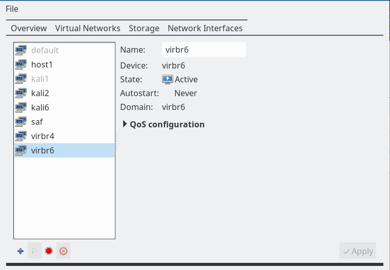
The variable “$IPTABLES” identifies the local iptables command. As already discussed in the last articles we arranged our (virtual) guest systems, the virtualization host and external systems in 3 defined host groups in FWbuilder (see the last post):
- br6_grp: kali3, kali4, kali5,
- br4_grp: kali2,
- ext_grp: the host and some external web server “lamp”.
Remember that rules for bridge-ports are investigated separately and independently as a packet moves from one bridge to another. Note that the host and further systems attached to “virbr4” via a veth device “vmh2” are recognized as members of a distinct logical host area for which iptables rules again are reinvestigated separatly by the kernel during packet transport. Therefore we need ACCEPT rules to allow for incoming and outgoing packets at the host’s interface “vmh2”.
Examples of spoofing scenarios
With 2 bridges in place we can define already a variety of ARP spoofing scenarios with a subsequent MiM-attack. We only test some selected, but typical scenarios. Note again that we cannot prevent the act of spoofing itself with iptables – however, we can prevent that redirected packets arrive at the MiM system.
Example 1: kali2 of virbr4 attacks the communication between kali3 and kali5 within virbr6
Which rule do we expect to prevent this? Actually as kali2 tries to redirect the intended communication from bridge virbr6 into bridge virbr4 we would already expect a DENY rule at the border port “vethb2” to stop redirected packets. In our rules list this would be rule 16.
So let us see. We start ARP spoofing on kali2:
root@kali2: ~# echo 1 > /proc/sys/net/ipv4/ip_forward
root@kali2: ~# iptables -A OUTPUT -p icmp --icmp-type redirect -j REJECT
root@kali2: ~# arpspoof -i eth3 -t 192.168.50.13 192.168.50.14 & 2> /dev/null
root@kali2: ~# arpspoof -i eth3 -t 192.168.50.14 192.168.50.13 & 2> /dev/null
eth3 is the relevant Ethernet interface to net 192.168.50.0/24 on guest kali2.
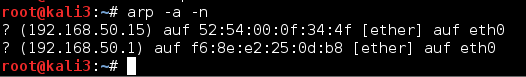
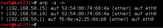
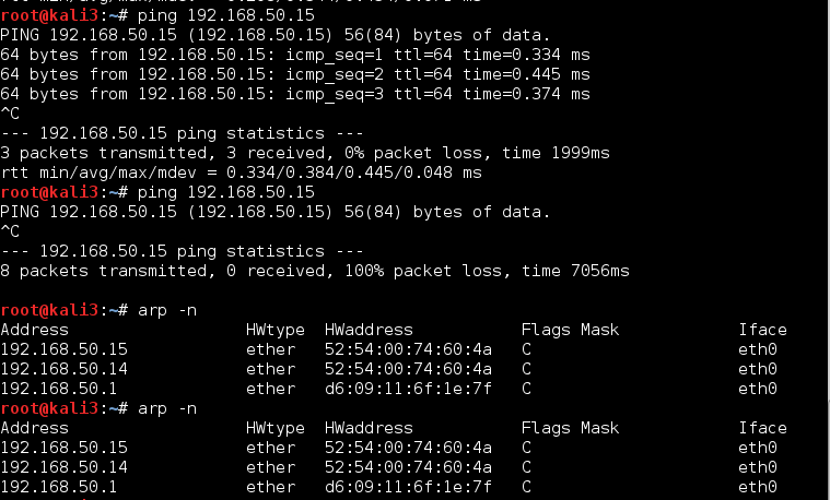
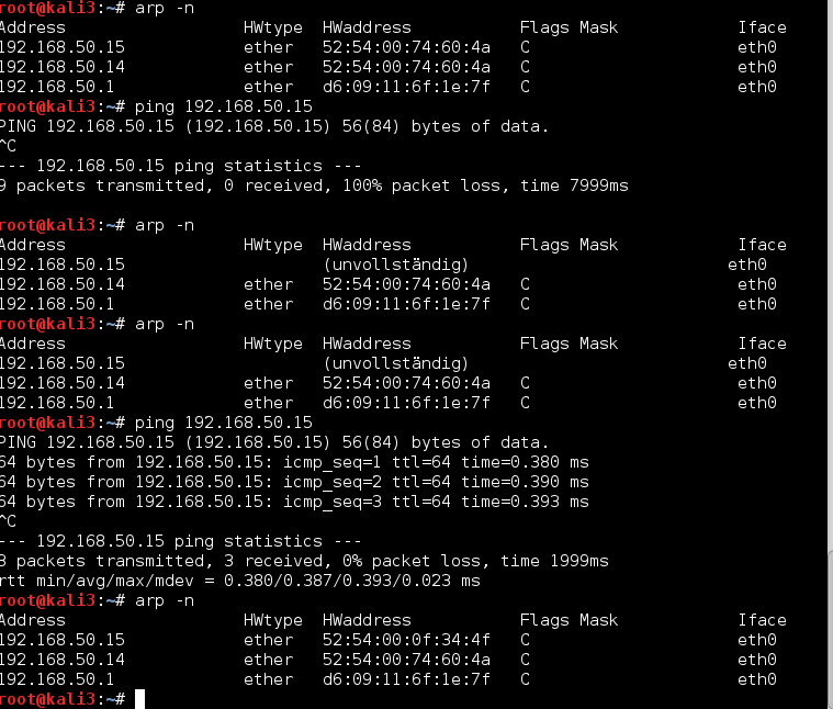
After some time we get the following ARP information on e.g. kali3:
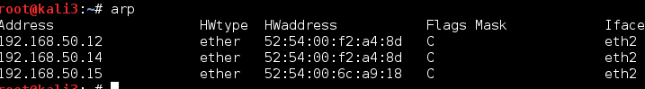
Consequently, after a “journalctl -f” on the virtualization host we find: :
Mar 17 13:21:53 mytux kernel: RULE 16 -- DENY IN=virbr6 OUT=virbr6 PHYSIN=vk63 PHYSOUT=vethb2 MAC=52:54:00:f2:a4:8d:52:54:00:b1:5d:1f:08:00 SRC=192.168.50.13 DST=192.168.50.14 LEN=84 TOS=0x00 PREC=0x00 TTL=64 ID=16140 DF PROTO=ICMP TYPE=8 CODE=0 ID=1756 SEQ=1
Mar 17 13:21:54 mytux kernel: RULE 16 -- DENY IN=virbr6 OUT=virbr6 PHYSIN=vk63 PHYSOUT=vethb2 MAC=52:54:00:f2:a4:8d:52:54:00:b1:5d:1f:08:00 SRC=192.168.50.13 DST=192.168.50.14 LEN=84 TOS=0x00 PREC=0x00 TTL=64 ID=16252 DF PROTO=ICMP TYPE=8 CODE=0 ID=1756 SEQ=2
Our test example shows that rules for border ports help to isolate bridges against misguided packets.
Rule 16 deserves a closer look as it contains a logical negation of 2 separately defined groups of hosts. We see that FWbuilder compiles the negation internally correctly: The related subchain definition contains all required hosts.
As described in the previous articles we stop the attack by the command “killall arpspoof” on kali2. Remember that due to time limits for ARP and port caching information on the guests and the bridge, respectively, it may take some time until normal operation is possible again. See the first article of this series for more information on this topic.
Example 2: kali2 of virbr4 attacks the communication between kali3 and the virtualization host
In this scenario a regular (!) packet would propagate from virbr6 through virbr4 and then to the host. Therefore, neither border port rules for virbr6 nor for virbr4 can block the traffic. We must, instead, rely on the analysis of redirected packets following an OUT direction to port vk42 – this is rule 5.
Therefore, this example is just a repetition of what we learned in the first article of this series
Linux bridges – can iptables be used against MiM attacks based on ARP spoofing ? – I
Actually, after another spoofing attack by kali2
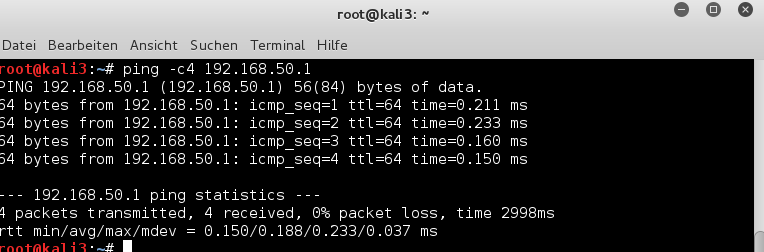
root@kali2: ~# arpspoof -i eth3 -t 192.168.50.1 192.168.50.13 & 2> /dev/null
root@kali2: ~# arpspoof -i eth3 -t 192.168.50.13 192.168.50.1 & 2> /dev/null
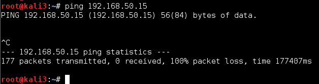
and sending pings from kali3 to the host we get:
Mar 17 18:44:51 mytux kernel: RULE 32 -- ACCEPT IN=virbr6 OUT=virbr6 PHYSIN=vk63 PHYSOUT=vethb2 MAC=54:00:f2:a4:8d:52:54:00:b1:5d:1f:08:00 SRC=192.168.50.13 DST=192.168.50.1 LEN=84 TOS=0x00 PREC=0x00 =64 ID=48428 DF PROTO=ICMP TYPE=8 CODE=0 ID=2872 SEQ=2
Mar 17 18:44:51 mytux kernel: RULE 5 -- DENY IN=virbr4 OUT=virbr4 PHYSIN=vethb1 PHYSOUT=vk42 MAC=52:50:f2:a4:8d:52:54:00:b1:5d:1f:08:00 SRC=192.168.50.13 DST=192.168.50.1 LEN=84 TOS=0x00 PREC=0x00 TTL ID=48428 DF PROTO=ICMP TYPE=8 CODE=0 ID=2872 SEQ=2
We see that the transition from bridge virbr6 to virbr4 works as planned – however the packets redirected to the MiM kali2 are stopped at vk42. Good!
Example 3: kali3 of virbr6 attacks the communication between kali4 of virbr4 and the virtualization host
We look at pings issued from the host to kali4 after an attack of kali3. In this case the border port rules again must not block. Instead, we rely on local port rules at port vk63, .i.e. rule 2. Indeed:
Mar 17 19:00:39 mytux kernel: RULE 43 -- ACCEPT IN= OUT=vmh2 SRC=192.168.50.1 DST=192.168.50.14 LEN=84 TOS=0x00 PREC=0x00 TTL=64 ID=53576 DF PROTO=ICMP TYPE=8 CODE=0 ID=2981 SEQ=1
Mar 17 19:00:39 mytux kernel: RULE 40 -- ACCEPT IN=virbr4 OUT=virbr4 PHYSIN=vmh1 PHYSOUT=vethb1 MAC=52:54:00:b1:5d:1f:7a:ff:fc:bd:68:b6:08:00 SRC=192.168.50.1 DST=192.168.50.14 LEN=84 TOS=0x00 PREC=0x00 TTL=64 ID=53576 DF PROTO=ICMP TYPE=8 CODE=0 ID=2981 SEQ=1
Mar 17 19:00:39 mytux kernel: RULE 2 -- DENY IN=virbr6 OUT=virbr6 PHYSIN=vethb2 PHYSOUT=vk63 MAC=52:54:00:b1:5d:1f:7a:ff:fc:bd:68:b6:08:00 SRC=192.168.50.1 DST=192.168.50.14 LEN=84 TOS=0x00 PREC=0x00 TTL=64 ID=53576 DF PROTO=ICMP TYPE=8 CODE=0 ID=2981 SEQ=1
Example 4: kali3 of virbr6 attacks the communication between kali2 and the virtualization host
In this case border rules should stop redirected packets. For our test case this would in particular be rule 18.
And – after the initialization of the attack by kali3 and the trial to send pings from kali2 to the host, we get:
Mar 18 16:47:30 mytux kernel: RULE 18 -- DENY IN=virbr4 OUT=virbr4 PHYSIN=vk42 PHYSOUT=vethb1 MAC=52:54:00:b1:5d:1f:52:54:00:f2:a4:8d:08:00 SRC=192.168.50.12 DST=192.168.50.1 LEN=84 TOS=0x00 PREC=0x00 TTL=64 ID=4405 DF PROTO=ICMP TYPE=8 CODE=0 ID=2420 SEQ=1
And vice versa :
Mar 18 16:48:42 mytux kernel: RULE 43 -- ACCEPT IN= OUT=vmh2 SRC=192.168.50.1 DST=192.168.50.12 LEN=84 TOS=0x00 PREC=0x00 TTL=64 ID=63251 DF PROTO=ICMP TYPE=8 CODE=0 ID=21778 SEQ=1
Mar 18 16:48:42 mytux kernel: RULE 18 -- DENY IN=virbr4 OUT=virbr4 PHYSIN=vmh1 PHYSOUT=vethb1 MAC=52:54:00:b1:5d:1f:f2:be:a1:5a:cd:6e:08:00 SRC=192.168.50.1 DST=192.168.50.12 LEN=84 TOS=0x00 PREC=0x00 TTL=64 ID=63251 DF PROTO=ICMP TYPE=8 CODE=0 ID=21778 SEQ=1
As expected!
Example 5: The host attacks communication between guests attached to an inner bridge
One may think such an example is just academic. Actually, in my opinion it is not. Although the administrator of a virtualization host has in principle a variety of means available to follow any communication across a bridge, ARP spoofing should NOT be such a measure under normal operation conditions. In addition, there may be legal aspects in a professional hosting situation.
But more important: From the perspective of the involved bridges, in our setup the host is attached to bridge virbr4 as an external guest over a border port. Rules for the virtualization host are, therefore, only an example for similar rules applied to other external hosts which may have the allowance to communicate with bridge guests – via forwarding and a respective route defined on the virtualization host.
We expect rule 20 to stop packages redirected by the MiM:
Mar 18 17:38:38 rux kernel: RULE 32 -- ACCEPT IN=virbr6 OUT=virbr6 PHYSIN=vk63 PHYSOUT=vethb2 MAC=f2:be:a1:5a:cd:6e:52:54:00:b1:5d:1f:08:00 SRC=192.168.50.13 DST=192.168.50.12 LEN=84 TOS=0x00 PREC=0x00 TTL=64 ID=36173 DF PROTO=ICMP TYPE=8 CODE=0 ID=2218 SEQ=1
Mar 18 17:38:38 rux kernel: RULE 20 -- DENY IN=virbr4 OUT=virbr4 PHYSIN=vethb1 PHYSOUT=vmh1 MAC=f2:be:a1:5a:cd:6e:52:54:00:b1:5d:1f:08:00 SRC=192.168.50.13 DST=192.168.50.12 LEN=84 TOS=0x00 PREC=0x00 TTL=64 ID=36173 DF PROTO=ICMP TYPE=8 CODE=0 ID=2218 SEQ=1
And vice versa
Mar 18 17:39:39 rux kernel: RULE 20 -- DENY IN=virbr4 OUT=virbr4 PHYSIN=vk42 PHYSOUT=vmh1 MAC=f2:be:a1:5a:cd:6e:52:54:00:f2:a4:8d:08:00 SRC=192.168.50.12 DST=192.168.50.13 LEN=84 TOS=0x00 PREC=0x00 TTL=64 ID=10910 DF PROTO=ICMP TYPE=8 CODE=0 ID=2730 SEQ=1
Mar 18 17:39:40 rux kernel: RULE 20 -- DENY IN=virbr4 OUT=virbr4 PHYSIN=vk42 PHYSOUT=vmh1 MAC=f2:be:a1:5a:cd:6e:52:54:00:f2:a4:8d:08:00 SRC=192.168.50.12 DST=192.168.50.13 LEN=84 TOS=0x00 PREC=0x00 TTL=64 ID=11113 DF PROTO=ICMP TYPE=8 CODE=0 ID=2730 SEQ=2
Summary
So, all in all, for our few examples we could verify that our recipe for setting up iptables rules in case of several linked Linux bridges with guests on one [KVM] virtualization host guided us correctly. After associating unique IP addresses with bridge ports we can define rules that block the transport of packets redirected to a MiM system – even when multiple bridges are present on the virtualization host. Additional and special rules for the bridges’ border ports help to prevent irregular traffic between defined groups of guests and/or external hosts.
Note that we only demonstrated this for specific allowance rules for the ICMP protocol. Yet, it is easy to understand that the very same principles should work for any protocol on level 4.