Multivariate Normal Distributions – II – random vectors and their covariance matrix

This post requires Javascript to display formulas!

This post series is based on notes I took when I recently studied the mathematical properties of Multivariate Normal Distributions [MNDs]. A motivation to publish the notes came from the analysis of a Machine Learning experiment: A Convolutional Autoencoder [CAE] trained on human face images had produced a MND in its latent space. But MNDs are, of course, relevant in other contexts, too.

In this post we take some preparatory steps: I want to introduce the term “random vector” to describe statistical multivariate distributions in vector form. We then have a look at the definition of a probability density function [pdf] in multiple dimensions. Furthermore we discuss linear transformations of a random vector, its expectation values and its covariance matrix. The latter both marks and quantifies (linear) relations between its components. I will also point out a simple but useful equation for the behavior of the covariance matrix when a matrix operates on its random vector. Eventually we also have a look at marginal distributions and their probability density function.

I will proceed not too formally and my discussion of the topics will not be really complete in a pure mathematical sense. On our way I will also remind you of some basic ideas and equations from statistics. People who are familiar with all the terms named above can jump over this post.

Random Vectors and multivariate distributions

Let us assume that we can describe an object of interest, e.g. in the context of an ML problem, by a set of n indexed, real-value variables sj. Instead of a manifest object we could also use n variables to characterize the result of a well defined experiment. When I speak of “objects below I include this more abstract option.

Each object can mathematically be represented by a data point in the ℝn. We simply relate each of the indexed coordinate axes of a corresponding Euclidean coordinate system with a certain object property. The coordinates of the data points are then given by the variable values.

Let us now order a complete set of parallel measured property values sjc for a concrete object as indexed components of a vector sc. The vector then represents our object:

\[ \pmb{s}^c \: = \: \left( \, s_1^c, \, s_2^c, \, ….\, s_n^c\, \right)^T \,
\]

The T indicates the transposition operation. Note: Throughout this post series we assume that untransposed vectors are written in vertical form. I.e. the components are arranged as rows.

Samples

Let us assume that we have m concrete observations of individual objects (or experimental results). The values of the n real variables for each object are always measured or qualified in parallel:

  • We either randomly pick a bunch of m concrete objects out of a wider population of available objects and determine the values of their n characteristic sj-variables.
  • Or we repeat a concrete experiment, whose outcome is described by values for a set of n measurable sj-variables, many times. The setup for our experiment defines precisely what the variables are and how we measure their values. The experimental result can be interpreted as an abstract “object”.

Thus we get samples of object data. Our experimental setup and the properties of our objects define a sample space Ω we have a clear description of how we produce one or multiple vectors s. A particular observation maps Ω to an individual vector.

Let us assume that at least in principle our vector components can take any real value. Producing a vector s can then formally be regarded as a function to ℝ:

FS: Ω   =>   ℝn,     s = FS(Ω, experiment number, … ).

A sequence of many observations, i.e. creating a sample, formally corresponds to a sequence of many independent applications of this function. An implicit (and sometime problematic) assumption is that picking multiple objects or our experiments do not influence Ω and the statistics of the basic population.

The outcome, namely a set of resulting s-vectors, depends on the statistical properties of the underlying object population. We index the k-th vector by sk.

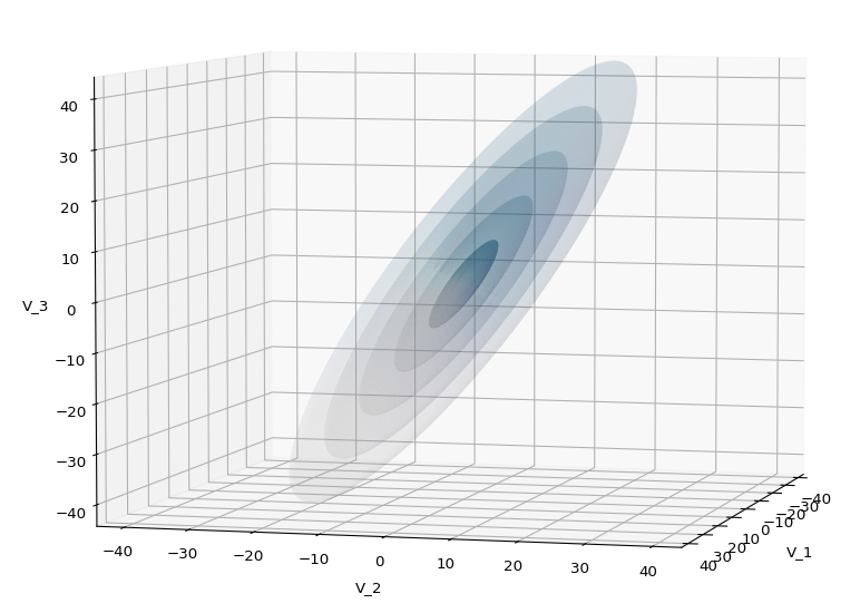
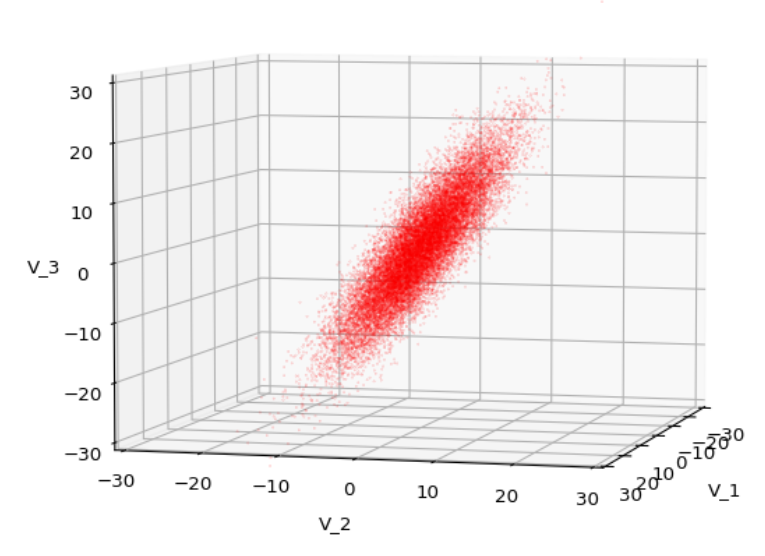
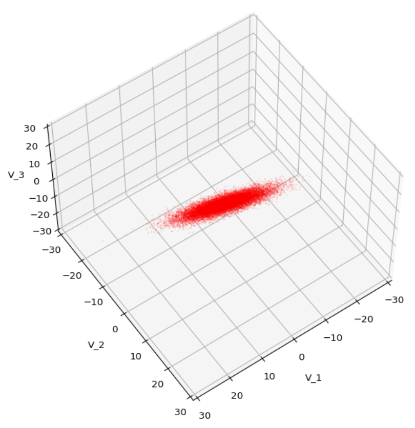
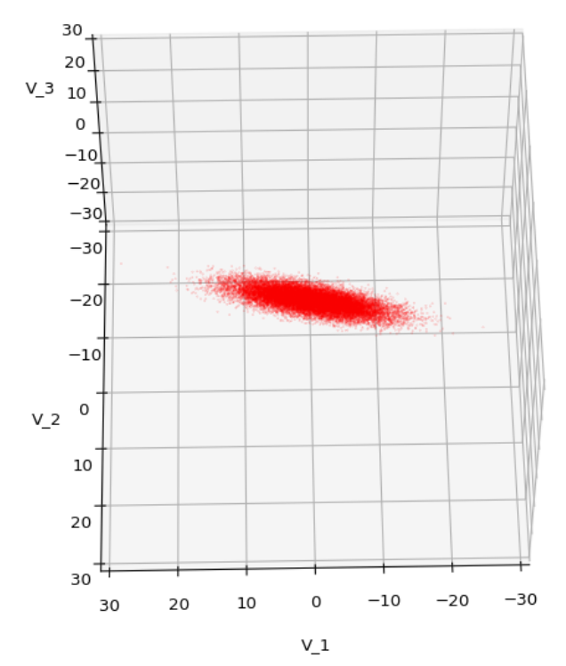
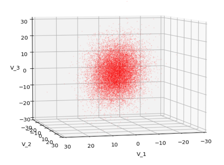
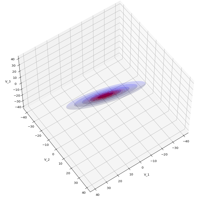
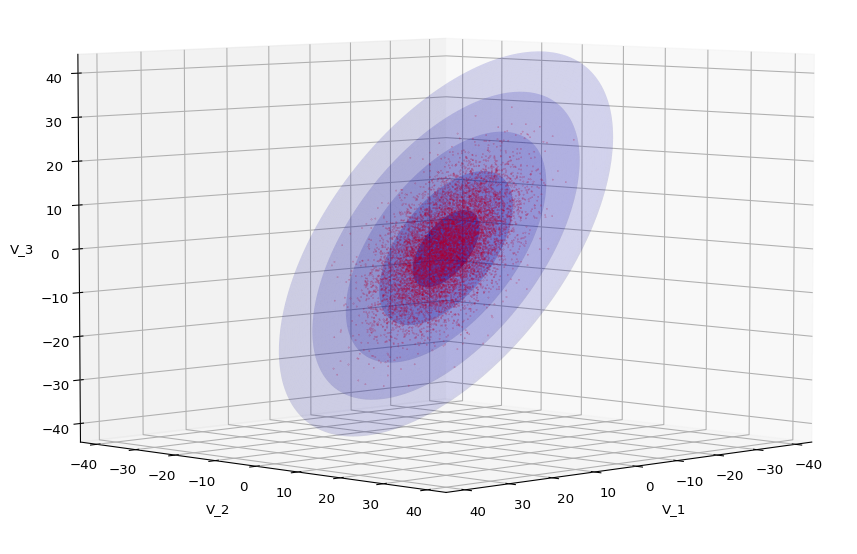
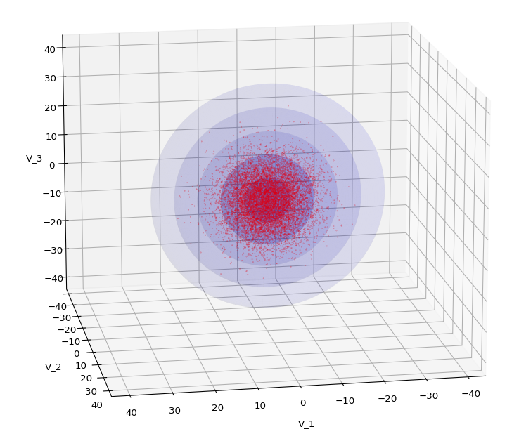
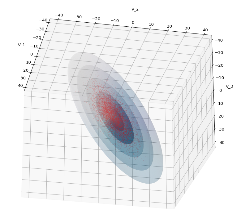
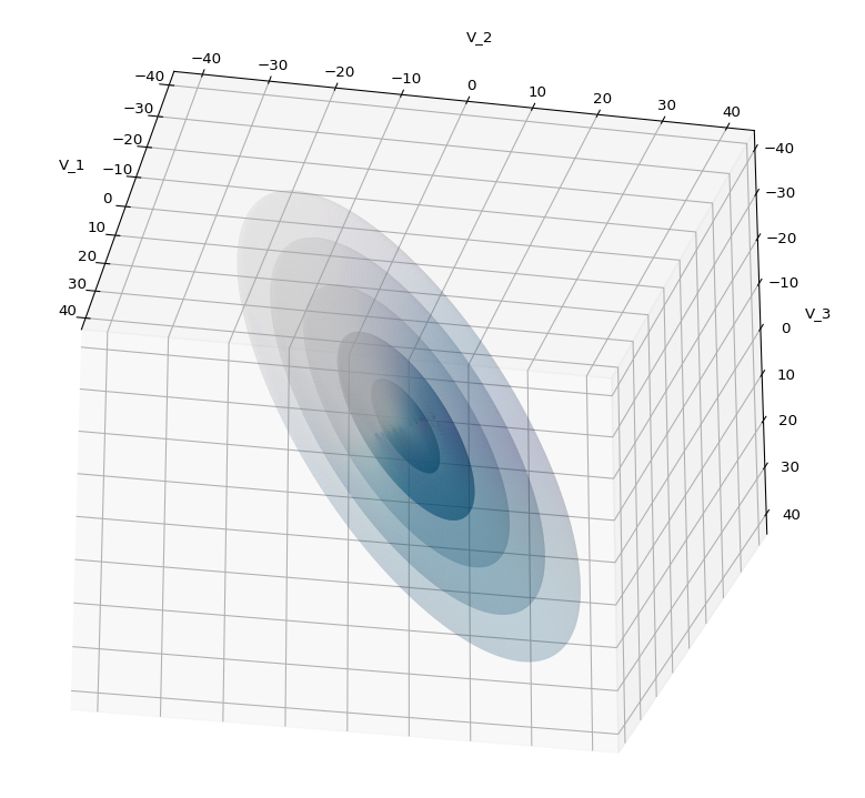
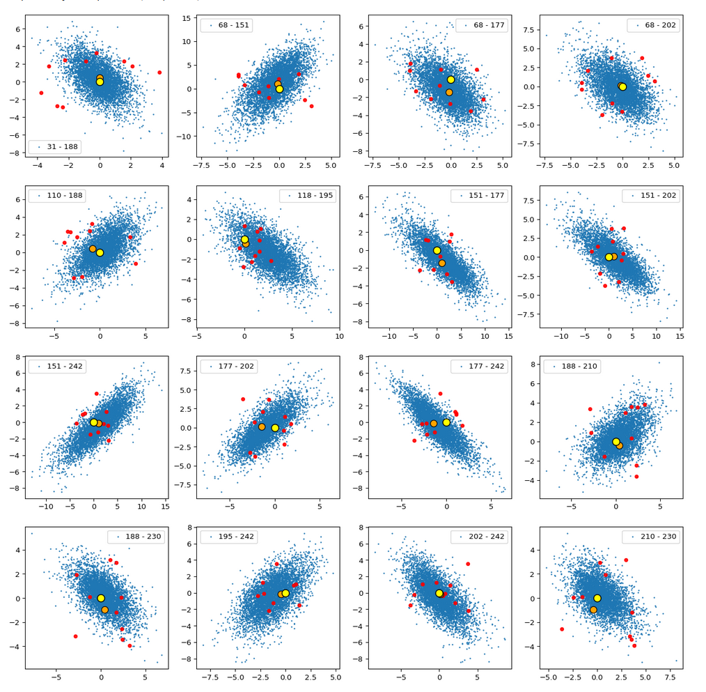
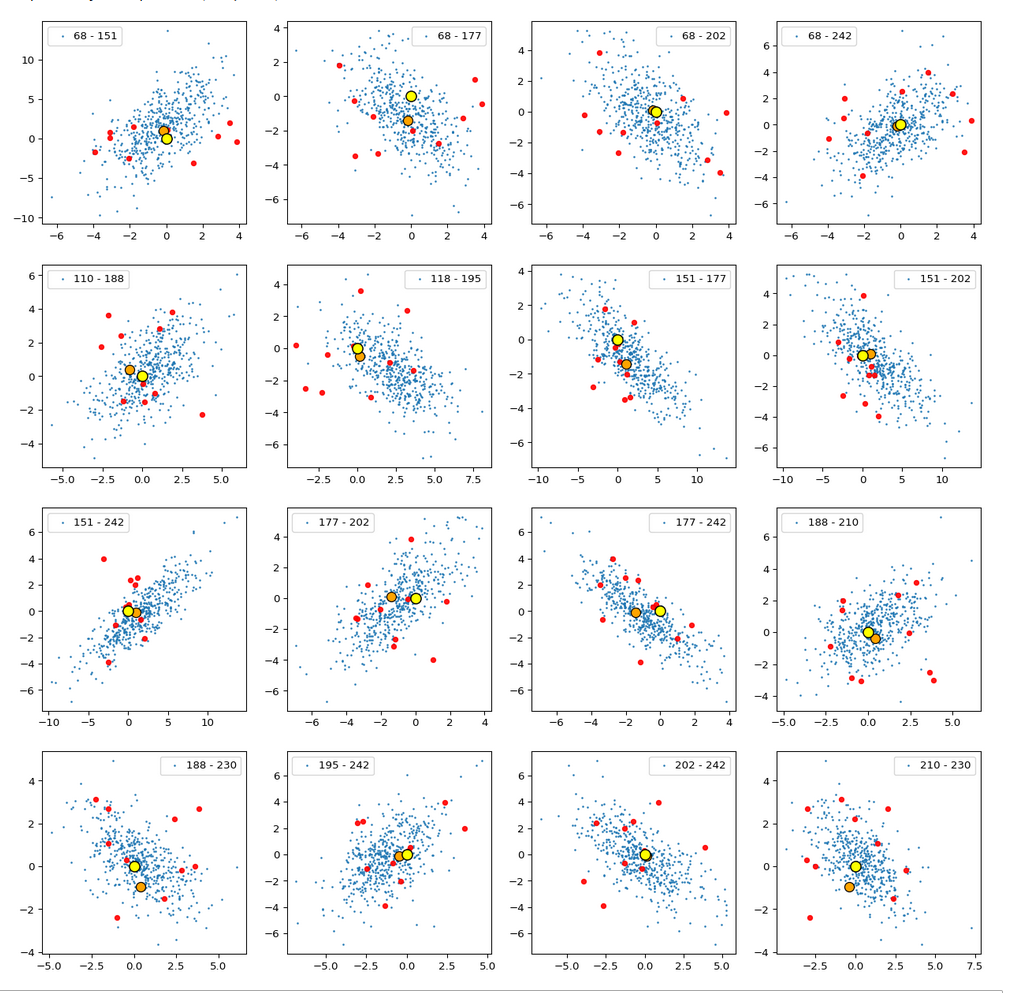
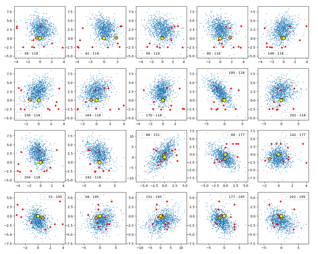
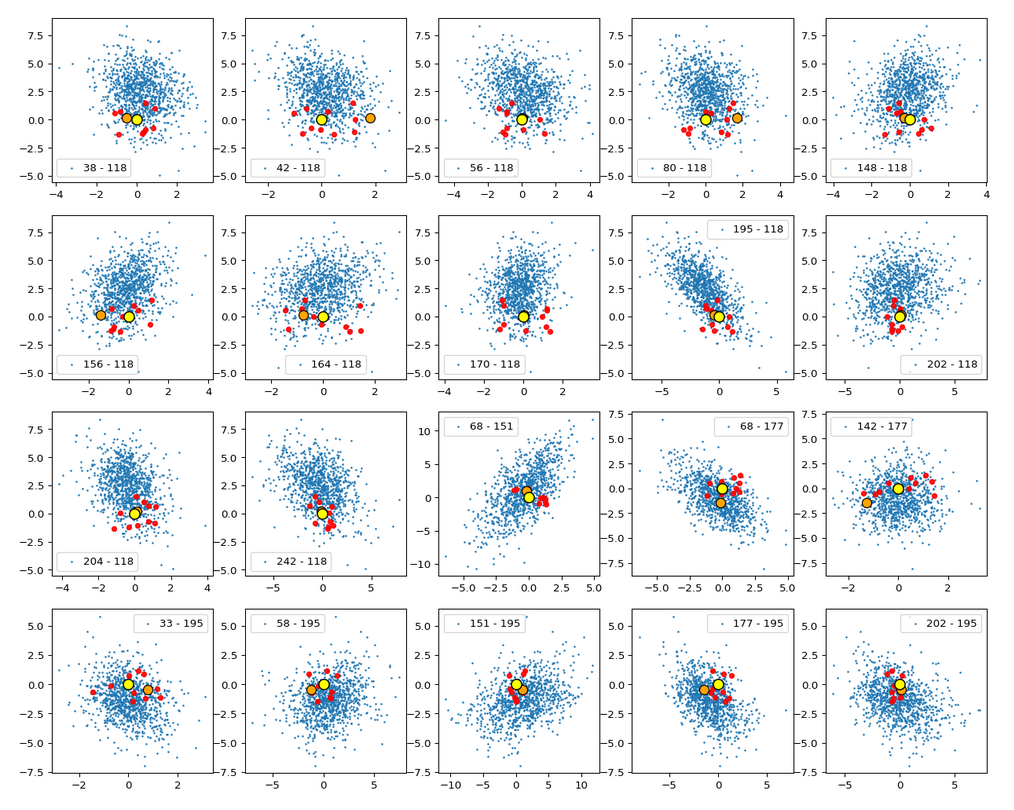
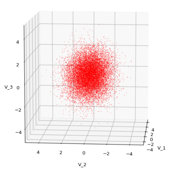
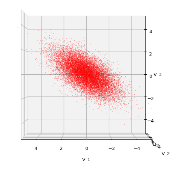
Each sample can be visualized by a bunch of data points in an n-dimensional space. A concrete sample in 3 dimensions may e.g. look like this from two perspectives:

But our sample can also be represented by a data matrix. We can e.g. arrange the columns to be given by the sk vectors. If we have a sample of m objects then we get a (n x m)- data matrix MS ∈ ℝnxm. A row with index j then provides us with a sample statistics for the j-th object property.

\[
\pmb{\operatorname{D}}_S \: = \: \begin{pmatrix}
s^1_1 & s^2_1 &\cdots & s^m_1 \\
s^1_2 & s^2_2 &\cdots & s^m_2 \\
\vdots &\vdots &\ddots &\vdots \\
s^1_n & s^2_n &\cdots & s^m_n \end{pmatrix}
\]
\[ \pmb{\operatorname{D}}_S \: = \: \left(\, \pmb{s}^1, \pmb{s}^2, \cdots …, \pmb{s}^m\right).
\]

Often you will find the transposed matrix for reasons of an efficient notation. I prefer this version as it later allows for matrix operations on the vector components from the left side, e.g. in a Python program.

Random vectors

We indicate the statistical element in creating a concrete vector from an underpinning population by a vector symbol S. By using this symbol we understand implicitly that any concrete vector S = sc is created by applying our well defined function FS.

It is natural to split S up into n individual univariate random variables Sj: Ω => ℝ, which represent the statistics per vector component. We write S in vector form:

\[ \pmb{S} \: = \: \left( \, S_1, \, S_2, \, ….\, S_n\, \right)^T
\]

So:

\[ \pmb{S} \:=\: \pmb{s}^c\: =: \left(\, S_1=s_1, S_2=s_2, \cdots …, S_n=s_n \, \right)^T.
\]

The vector variable S gets concrete component values by a well defined statistical process. But, if you like to see it more globally, S represents any object from the population and thus in a certain meaning the whole population – and its statistics.

We call S a multivariate random variable or a random vector.

Thus, our statistical multivariate distribution can now be represented by a random vector – and we know how to create samples by turning S repeatedly into concrete vectors. Why all the fuss?

Linear operations on random vectors

The vector notation allows us to combine a random vector with mathematical vector operations, in particular linear transformations. We implicitly understand that such an operation is applied to any vector of the population (and in certain contexts also to elements of our samples). Such a transformation consists of a mapping of vectors of the original population or a sample to new vectors in the same or a different vector space by one and the same linear transformation. The mapping gives us new component values.

In linear algebra we learn that a linear vector transformation can be represented by a matrix plus a translation vector. If the transformation maps a random vector S of the ℝm to a random vector X into the ℝn then the linear (affine) transformation is defined by a (n x m)-matrix A ∈ ℝnxm and a vector b ∈ ℝn:

\[ \begin{align}
\pmb{x} \,&=\, (x_1, x_2, …, x_n)^T \,=\, \pmb{\operatorname{A}} \pmb{s} \, + \, \pmb{b} \\
&\, \\
\pmb{X} \, &= \, \pmb{\operatorname{A}S} + \pmb{b} \end{align}
\]

In close similarity to standard operations in vector spaces a linear transformation of a random vector can have two meanings:

  • The operation either actively transforms our random vector (and the underlying vector distribution) – e.g. by a rotation in the ℝn.
  • Or we perform a passive switch to another Euclidean coordinate system (e.g. by a rotation of the coordinate axes) and the transformation adapts the component values accordingly.

Invertible transformations?

If and when we have a transformation within the ℝn the matrix A would typically be a real valued quadratic (n x n)-matrix. In many cases we will assume that the transformation and its matrix A are invertible. This imposes certain conditions on the matrix: A must then be positive definite and have a determinant det(A) ≠ 0.

\[ \operatorname{det}\left(\pmb{\operatorname{A}}\right) \, =\, \left|\pmb{\operatorname{A}}\right|
\, \ne \, 0
\]

But note that in the more general case also rectangular matrices can have a “left”- or a “right”-inverse matrices; see https://en.wikipedia.org/ wiki/ Generalized_ inverse.

Rectangular matrices, e.g. with m (< n) rows and n columns have a rank rm < n, and not all of the column vectors of the matrix are linearly independent.

Probability density functions in the ℝn

Let us assume that the population behind a random vector covers the ℝn completely and in a continuous way. By “continuous” we mean that a transition to infinitesimal small volumes at any position in the ℝn is possible: We still will find vectors of the population there and component values change smoothly between adjacent elements.

We can apply a frequency analysis to the vector component values of the objects of a huge sample or of a number of samples. E.g. we can define intervals into which the components may fall or not. The analysis gives us a probability P(S=sΔV) for the occurrence of position vectors sΔV which point into a certain finite region ΔV of the ℝn.

If you better like to think in terms of data points:

We get a probability that a data point representing a statistically picked object lies within a certain defined and finite region of the ℝn.

How we split up the ℝn into separate volume regions depends on available information about the object population or on an analysis of sufficiently large samples.

If each component of the vectors s can take any real value we may under certain circumstances make a transition to probability densities. Probability densities can be distilled from huge samples or alternatively very many samples picked from the underlying population. To get an idea of the density function we, in practice, raise the number of observations and reduce the volume regions of the ℝn to a proper averaging size that avoids wild fluctuations. The latter is called “sampling”.

If we by many experiments can assume a converging limiting process to infinitesimal real value intervals dsj for each of the vector components then we end up with a bunch of n continuous 1-dim probability density functions pj(sj): ℝ => ℝ. A concrete probability value for a component must be derived via integration of pj() over a finite interval a ≤ s_j ≤ b:

\[ \operatorname{P}(a \le s_j \le b) \,=\, \int_a^b p(s_j)ds_j
\]

An interpretation as a probability requires, of course, a normalization of such an integral over the whole ℝ.

It is clear that the full probability density function pS(s) of the vector distribution varies continuously with the 1-dim probability density functions of its components.

In this post series we are interested in examples of vector distributions which can be described by a continuous multidimensional probability density function [p.d.f] for infinitesimal volume elements dVS = ds1, ds2dsn:

\[ p_{\pmb{S}}(\pmb{s}) \: = \: p_{\pmb{S}} \left( \, s_1, \, s_2, \, ….\, s_n\, \right)
\]
\[ \begin{align} P(\pmb{s}, V) \, &= \, \int_V p_{\pmb{S}}(\pmb{s}) \, ds_1ds_2…ds_n \\
&= \, \int\int…\int_V p_{\pmb{S}} \left( \, s_1, \, s_2, \, ….\, s_n\, \right) \, ds_1ds_2 \cdots ds_n
\end{align}
\]

where V marks some finite volume element in ℝn. Note again: A normalization of such an integral over the whole ℝn is required to get well defined probability values. The normalization factor above is assumed to be integrated in the mathematical expression for pS(s).

For the purposes of this post series we assume that both pS and the pj() are differentiable.

Correlations of random vector components

There may be dependencies which control how the components of a random vector vary together. So the variation of pS(s) may depend in a rather complicated way on the density functions of their components pj(sj)

\[ p_{\pmb{S}}(\pmb{s}) \: = \: p_{\pmb{S}} \left( \, p_1(s_1), \, p_2(s_2), \, ….\, p_n(s_n) \, \right)
\]

The variation of components may e.g. happen in pairwise correlated or uncorrelated ways. I.e. we can in general not assume that the total probability density function pS(s) for a random vector is e.g. a product of the 1-dimensional density probability functions pj(sj for its components.

Such dependencies make the statistics of multivariate vector distributions more complex than the statistics of their constituting (marginal) univariate components. The relation between pS and the individual pj can be difficult to derive and it may even reflect non-linear component relations. Luckily we will see that MNDs contain only linear couplings of the components and thus simple correlations described by constant coefficients.

In ML we have only samples with a limited number of individual vectors available. The investigated samples have to be big enough to reveal the properties of the total probability density function pS(s), which assumedly describes the variation of the underlying continuous vector population in the ℝn.

Probability density after linear transformations and contour hyper-surfaces

A transformation of the components of a random vector has, of course, also an impact on the resulting probability density:

\[ p_{\pmb{X}}(\pmb{x}) \,=\, p_{\pmb{X}} \left( \pmb{\operatorname{A}s} \,+\, \pmb{b} \right) \, = \, p_{\pmb{X}} \left(\, x_1, \, x_2, \, ….\, x_n\, \right)
\]

and for a finite volume VX in the target space

\[ P\left(\pmb{x}, V_X\right) \,=\, \int\int…\int_{V_X} \, = \, p_{\pmb{X}} \left( x_1, \, x_2, \, ….\, x_n \right)\, dx_1dx_2 \cdots dx_n
\]

In case of a well defined distribution S we can hope to find an analytical expression for the multidimensional probability pX(x) of the transformed random vector X. But as we will see we have to invest some work into the calculation. And we will answer the question by what parameters the probability density of a MND is defined in a unique way.

We expect that the concrete form of pX is influenced in a characteristic way by the properties of the original pj(sj)-pdfs and, of course, by our transformation matrix A. This is the case for MNDs and we will study the effects of linear transformations on MNDs and their projections to sub-spaces in more detail in forthcoming posts.

As the matrix A mixes components we may also expect the creation of (linear) relations between the X-components. Therefore, the shape of the density distribution may change due to scaling, mirroring, shearing and rotation effects. This results from the fact that linear transformations are affine transformations in geometrical terms.

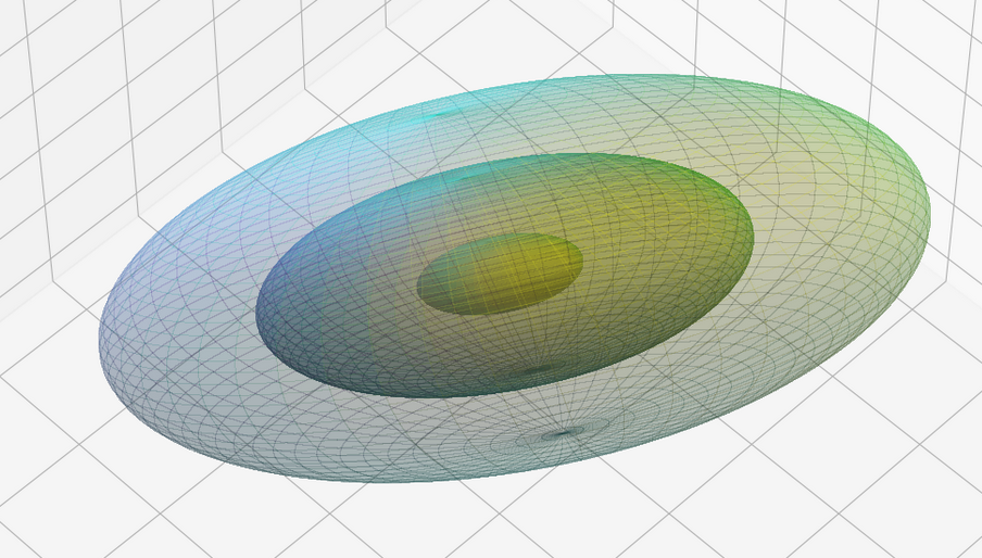
This leads to the question by what method we can describe the “shape” of a multivariate distribution. A simple method is to determine hyper-surfaces of constant probability density values. I.e. contour-surfaces:

\[ p_{\pmb{X}}(\pmb{x}) \, = \, p_{\pmb{X}} \left(\, x_1, \, x_2, \, ….\, x_n\, \right) \:=\: const.
\]

This actually is the definition of a (n-1)-dimensional hypersurface. The dependency on the component values can be complicated. But for the special case of a MND we will find a rather comprehensible form which we can interpret. So we will get a chance to understand and qualify the effects of a linear transformation by its impact on the contour hyper-surfaces of the probability density of a MND.

Expectation value and covariance of a statistical vector distribution

The covariance of two univariate distributions X and Y is defined as

\[
\begin{align}
\operatorname{cov}(X, Y)
&= \operatorname{\mathbb{E}}\left[\,\left(\,X \,-\, \operatorname{\mathbb{E}}\left(X\right)\,\right) \, \left(\,Y \,-\, \operatorname{\mathbb{E}}\left(Y\right)\, \right)\,\right] \\
&= \operatorname{\mathbb{E}}\left(X Y\right) \,-\, \operatorname{\mathbb{E}}\left(X\right) \operatorname{\mathbb{E}}\left(Y\right)
\end{align}
\]

The expectation value and the covariance of a general vector distribution S are defined by:

\[ \begin{align} \pmb{\mu}\left(\pmb{S}\right) \,=\, \pmb{\mu}_S \: &= \: \operatorname{\mathbb{E}}\left(\pmb{S} \right) \, := \, \left( \operatorname{\mathbb{E}}(S_1), \, \operatorname{\mathbb{E}}(S_2), …, \, \operatorname{\mathbb{E}}(S_n) \right)^T \\
\operatorname{Cov}\left(\pmb{S}\right) \: &:= \: \operatorname{\mathbb{E}}\left[\left(\pmb{S} – \operatorname{\mathbb{E}}(\pmb{S}) \right)\, \left(\pmb{S} – \operatorname{\mathbb{E}}(\pmb{S}) \right)^T \right] \end{align}
\]

Note the order of transposition in the definition of Cov! A (vertical) vector is combined with a transposed (horizontal) vector. The rules of a matrix-multiplication then give you a matrix as the result! And the expectation value has to be taken for every element of the matrix.

Thus, the interpretation of the notation given above is:

Pick all pairwise combinations (Sj, Sk) of the component distributions. Calculate the covariance of the pair cov(S_j, S_k) and put it at the (j,k)-place of the matrix.

Meaning:

\[ \begin{align}
\operatorname{Cov}\left(\pmb{S}\right)\:&=\:\operatorname{\mathbb{E}} {\begin{pmatrix} (S_{1}-\mu_{1})^{2}&(S_{1}-\mu_{1})(S_{2}-\mu_{2})&\cdots &(S_{1}-\mu_{1})(S_{n}-\mu_{n})\\(S_{2}-\mu_{2})(S_{1}-\mu_{1})&(S_{2}-\mu_{2})^{2}&\cdots &(S_{2}-\mu _{2})(S_{n}-\mu_{n})\\\vdots &\vdots &\ddots &\vdots \\(S_{n}-\mu_{n})(S_{1}-\mu_{1})&(S_{n}-\mu_{n})(S_{2}-\mu _{2})&\cdots &(X_{n}-\mu_{n})^{2} \end{pmatrix}}
\\\\
&=\quad {\begin{pmatrix} \operatorname{Var} (S_{1})&\operatorname{Cov} (S_{1},S_{2})&\cdots &\operatorname{Cov} (S_{1},S_{n})\\ \operatorname{Cov} (S_{2},S_{1})&\operatorname{Var} (S_{2})&\cdots &\operatorname{Cov} (S_{2},S_{n})\\\vdots &\vdots &\ddots &\vdots \\ \operatorname{Cov} (S_{n},S_{1})&\operatorname{Cov} (S_{n},S_{2})&\cdots &\operatorname {Var} (S_{n}) \end{pmatrix}}
\end{align}
\]

Keep the details of this definition in mind!

The above matrix is the (variance-) covariance matrix. As Wikipedia tells you, some people call it a bit different. I refer to it later on just as the covariance matrix (of a random vector).

Useful properties of the covariance matrix of a random vector

Note that the diagonal elements of the covariance matrix are just the variances of the individual component distributions, whilst the off diagonal elements contain the pairwise covariances of the vector components. In case of a vector distribution with uncorrelated (or even independent) Sj the matrix becomes diagonal:

\[
\begin{pmatrix}
(\sigma_1^s)^2 & 0 &\cdots & 0 \\
0 & (\sigma_2^s)^2 &\cdots & 0 \\
\vdots &\vdots &\ddots &\vdots \\
0 & 0 &\cdots & (\sigma_n^s)^2 \end{pmatrix}
\]


Other properties can be derived from the linearity of expectation values and the fact that

\[ \begin{align} \operatorname{Cov}\left(aX+bY,\,cW+dV\right) \,=\, ac*\operatorname{Cov}\left(X,\, W\right)\,&+\,ad*\operatorname{Cov}\left(X,\,V\right)\,\\ +\,bc*\operatorname{Cov}\left(Y,\,W\right)\,&+\,bd*\operatorname{Cov}\left(Y,\,V\right) \end{align}
\]

It is relatively easy to show that the defined expectation value of a vector distribution behaves linearly with respect to linear transformations of S with a matrix A:

\[
\operatorname{\mathbb{E}}\left( \pmb{\operatorname{A}S} + \pmb{b} \right) \, = \pmb{\operatorname{A}} \operatorname{\mathbb{E}}\left(\pmb{S} \right) \,+\, \pmb{b} \vphantom{(}
\]

And the covariance matrix Cov transforms as follows:

\[ \begin{align}
\operatorname{Cov}\left(\pmb{\operatorname{A}S}\right) \: &= \: \operatorname{\mathbb{E}}\left[\, \left( \pmb{\operatorname{A}} (\pmb{S} \,-\, \mu_S ) \right) \, \left( \pmb{\operatorname{A}} (\pmb{S} \,-\, \mu_S ) \right)^T \, \right] \\ &= \: \operatorname{\mathbb{E}}\left[\, \pmb{\operatorname{A}} ( \pmb{S} \,-\, \mu_S ) \, (\pmb{S} \,-\, \mu_S)^T \pmb{\operatorname{A}}^T \,\right] \\
&= \: \pmb{\operatorname{A}} \operatorname{\mathbb{E}}\left[\, ( \pmb{S} \,-\, \mu_S ) \, (\pmb{S} \,-\, \mu_S)^T \,\right] \pmb{\operatorname{A}}^T \\
\operatorname{Cov}\left(\pmb{\operatorname{A}S}\right) \: &= \: \pmb{\operatorname{A}} \operatorname{Cov}\left(\pmb{S}\right) \pmb{\operatorname{A}}^T \end{align}
\]

The intermediate steps for the Cov – and in particular the 3rd one – are in my opinion best understood when you just write the stuff down for e.g. (3×3)-matrices and carefully regard the Cov-definition for random vectors. You will see that the definition of Cov just allows for the right index juggling! The extension to more dimensions is straightforward and could formally be done by induction.

See e.g. also https://cds.nyu.edu/ wp-content/ uploads/ 2021/05/ covariance_matrix.pdf and https://stats.stackexchange.com/ questions/ 113700/ covariance-of-a-random-vector-after-a-linear-transformation.

Other useful properties are

\[
\begin{align}
\operatorname{Cov}\left(V_j,\, V_k\right) \,&=\, \operatorname{\mathbb{E}}\left(V_j, \,V_k\right) \,-\, \operatorname{\mathbb{E}}\left(V_j\right)\operatorname{\mathbb{E}}\left(V_k\right) \\
\operatorname{Cov}\left(\pmb{S}\right) \,=\,
\operatorname{Cov}\left(\pmb{S},\, \pmb{S}\right) \,&=\, \operatorname{\mathbb{E}}\left(\pmb{S}, \,\pmb{S}^T\right) \,-\, \operatorname{\mathbb{E}}\left(\pmb{S}\right)\operatorname{\mathbb{E}}\left(\pmb{S}\right)^T
\end{align}
\]

By the way, for two different random vectors X and Y the matrix

\[
\operatorname{Cov}\left(\pmb{X},\, \pmb{Y}\right) \,=\, \operatorname{\mathbb{E}}\left(\pmb{X}, \,\pmb{Y}^T\right) \,-\, \operatorname{\mathbb{E}}\left(\pmb{X}\right)\operatorname{\mathbb{E}}\left(\pmb{Y}\right)^T
\]

is called the cross-covariance matrix.

Remark on independence and correlation

Two univariate random variables X and Y are statistically (!) independent when their joint probability, i.e. their probability for the occurrence of a value pair (x,y) is the product of the individual probabilities for the occurrence of x and y:

\[
p_{X,Y}(x,y) \,=\, p_X(x)*p_Y(y)
\]

However, uncorrelatedness does mean something else, namely that the covariance of the distributions is 0:

\[ \begin{align}
\operatorname{Cov}\left(X,\, Y\right) \,&=\, 0 \\
\Rightarrow \: \operatorname{\mathbb{E}}\left(X Y\right) \,&=\, \operatorname{\mathbb{E}}\left(X\right) \operatorname{\mathbb{E}}\left(Y\right)
\end{align}
\]

Independence and uncorrelatedness are two different (!) things and uncorrelatedness does in general not imply statistical independence!

Thus the uncorrelatedness of a pair of components (Sj, Sk) of a random vector S does unfortunately not automatically imply their independence!

We shall later in this series that this is actually a bit different for a MND.

Conclusion

In this post we have collected and clarified some basic terms which we will use in forthcoming texts about multivariate normal distributions. An important step was to describe a statistical vector distribution in form of a random vector. We also have seen that a random vector can be subject to linear transformations.

We have discussed a limiting transition to probability density functions for statistical vector distributions. We understood that dependencies and correlations may make it difficult to derive the form of the probability density for the random vector from the probability density functions for the vector components.

In addition we have defined the mean value and the covariance matrix for a random vector. We saw how a linear transformation affects the covariance matrix.

In the next post we will apply our knowledge to a simple random vector based on Gaussian probability density functions without correlations. We will study what effects orthogonal and shearing transformations have on such a distribution.


How to plot a tri-variate data distribution in 3D and add surfaces of confidence ellipsoids from a trivariate normal distribution with the same covariance matrix

This post requires Javascript to display formulas!

In Machine Learning [ML] or statistics it is interesting to visualize properties of multivariate distributions by projecting them into 2- or 3-dimensional sub-spaces of the datas’ original n-dimensional variable space. The 3-dimensional aspects are not so often used because plotting is more complex and you have to fight with transparency aspects. Nevertheless a 3-dim view on data may sometimes be more instructive than the analysis of 2-dim projections. In this post we care about 3-dim data representations of tri-variate distributions X with matplotlib. And we add ellipsoids from a corresponding tri-variate normal distribution with the same covariance matrix as X.

Multivariate normal distribution and their projection into a 3-dimensional sub-space

A statistical multivariate distribution of data points is described by a so called random vector X in an Euclidean space for the relevant variables which characterize each object of interest. Many data samples in statistics, big data or ML are (in parts) close to a so called multivariate normal distribution [MND]. One reason for this is, by the way, the “central limit theorem”. A multivariate data distribution in the ℝn can be projected orthogonally onto a 3-dimensional sub-space. Depending on the selected axes that span the sub-space you get a tri-variate distribution of data points.

Whilst analyzing a multivariate distribution you may want to visualize for which regions of variable values your projected tri-variate distributions X deviate from adapted and related theoretical tri-variate normal distributions. The relation will be given by relevant elements of the covariance matrix. Such a deviation investigation defines an application “case 1”.

Another application case, “case 2”, is the following: We may want to study a 3-variate MND, a TND, to get a better idea about the behavior of MNDs in general. In particular you may want to learn details about the relation of the TND with its orthogonal projections onto coordinate planes. Such projections give you marginal distributions in sub-spaces of 2 dimensions. The step from analyzing bi-variate to analyzing tri-variate normal distributions quite often helps to get a deeper understanding of MNDs in spaces of higher dimension and their generalized properties.

When we have a given n-dimensional multivariate random vector X (with n > 3) we get 3-dimensional data by applying an orthogonal projection operator P on the vector data. The relatively trivial operator projects the data orthogonally into a sub-volume spanned by three selected axes of the full variable space. For a given random vector their will, of course, exist multiple such projections as there is a whole bunch of 3-dim sub-spaces for a big n. In “case 2”, however, we just create basic vectors of a 3-dim MND via a proper random generation function.

Regarding matplotlib for Python we can use a scatter-plot function to visualize the resulting data points in 3D. Typically, plots of an ideal or approximate tri-variate normal distribution [TND] will show a dense ellipsoidal core, but also a diffuse and only thinly populated outer region. To get a better impression of the spatial distribution of X relative to a TND and the orientation of the latter’s main axes it might be helpful to include ideal contour surfaces of the TND into the plots.

It is well known that the contour surfaces of multivariate normal distributions are surfaces of nested ellipsoids. On first sight it may, hower, appear difficult to combine impressions of such 2-dim hyper-surfaces with a 3-dim scatter plot. In particular: Where from do we get the main axes of the ellipsoids? And how to plot their (hyper-) surfaces?

Objective of this post

The objective of this post is to show that we can derive everything that is required

  • to plot general tri-variate distributions
  • plus ellipsoids from corresponding tri-variate normal distributions

from the covariance matrix Σ of our random vector X.

In case 2 we will just have to define such a matrix – and everything else will follow from it. In case 1 you have to first determine the (n x n)-covariance matrix of your random vector and then extract the relevant elements for the (3 x 3)-covariance matrix of the projected distribution out of it.

The result will be plots like the following:

The first plot combines a scatter plot of a TND with ellipsoidal contours. The 2nd plot only shows contours for confidence levels 1 ≤ σ ≤ 5 of our ideal TND. And I did a bit of shading.

How did I get there?

The covariance matrix determines everything

The mathematical object which characterizes the properties of a MND is its covariance matrix (Σ). Note that we can determine a (n x n)-covariance matrix for any X in n dimensions. Numpy provides a function cov() that helps you with this task. The relevant elements of the full covariance matrix for orthogonal projections into a 3-dim sub-space can be extracted (or better: cut out) by applying a suitable projection operator. This is trivial: Just select the elements with the (i, i)- and (i, j)-indices corresponding to the selected axes of the sub-space. The extracted 9 elements will then form the covariance matrix of the projected tri-variate distribution.

In case 2 we just define a (3 x 3)-Σ as the starting point of our work.

Let us assume that we got the essential Σ-matrix from an analysis of our distribution data or that we, in case 2, have created it. How does a (3 x 3)-Σ relate to ellipsoidal surfaces that show the same deformation and relations of the axes’ lengths as a corresponding tri-variate normal distribution?

Creation of a MND from a standardized normal distribution

In general any n-dim MND can be constructed from a standardized multivariate distribution of independent (and consequently uncorrelated) normal distributions along each axis. I.e. from n univariate marginal distributions. Let us call the standardized multivariate distribution SMND and its random vector Z. We use the coordinate system [CS] where the coordinate axes are aligned with the main axes of the SMND as the CS in which we later also will describe our given distribution X. Furthermore the origin of the CS shall be located such that the SMND is centered. I.e. the mean vector μ of the distribution shall coincide with the CS’s origin:

\[ \pmb{\mu} \: = \: \pmb{0}
\]

In this particular CS the (probability) density function f of Z is just a product of Gaussians gj(zj) in all dimensions with a mean at the origin and standard deviations σj = 1, for all j.

With z = (z1, z2, …, zn) being a position vector of a data point in the distribution, we have:

\[ \begin{align} \pmb{\mu} \: &= \: \pmb{0} \\
f_{\pmb{Z}} \:&=\: \pmb{\mathcal{N}}_n\left(\pmb{0}, \, \pmb{\operatorname{I}}_n \right) \:=\: \pmb{\mathcal{N}}_n\left(\pmb{\mu}=0 ,\, \pmb{\operatorname{\Sigma}}=\pmb{\operatorname{I}}_n \right)
\end{align}
\]

and in more detail

\[ \begin{align} f_{\pmb{Z}}(\pmb{z}) \, =\, \pmb{\mathcal{N}}_n\left(\pmb{0}, \, \pmb{\operatorname{I}}_n \right) \: &= \: \prod\limits_{j=1}^n g(z_j, \, \mu_j=0, \, \sigma_j=1) \\
&= \, {1 \over \sqrt{(2\pi)^n} } \,
{\large e}^{ – \, {\Large 1 \over \Large 2} {\Large \sum\limits_{j=1}^n} \, {\Large z_j}^2 } \\
&=\, {1 \over \sqrt{(2\pi)^n} } \,
{\large e}^{ – \, {\Large 1 \over \Large 2} {\Large \pmb{z}^T\pmb{z}} } \end{align}
\]

The construction recipe for the creation of a general MND XN from Z is just the application of a (non-singular) linear transformation. I.e. we apply a (n x n)-matrix onto the position vectors of the data points in the ℝn. Let us call this matrix A. I.e. we transform the random vector Z to a new random vector XN by

\[ \pmb{X}_N \: = \: \pmb{\operatorname{A}} \circ \pmb{Z}
\]

The resulting symmetric (!) covariance matrix ΣX of XN is given by

\[ \pmb{\operatorname{\Sigma}}_X \: = \: \pmb{\operatorname{A}} \pmb{\operatorname{A}}^T
\]

Σ determines the shape of the resulting probability distribution completely. We can reconstruct an A’ which produces the same distribution by an eigendecomposition of the matrix ΣX. A’ afterward appears as a combination of a rotation and a scaling. An eigendecomposition leads in general to

\[ \pmb{\operatorname{\Sigma}}_{X_N} \: = \: \pmb{\operatorname{V}} \pmb{\operatorname{D}} \pmb{\operatorname{V}}^{-1}
\]

with V being an orthogonal matrix and D being a diagonal matrix. In case of a symmetric, positive-definite matrix like our Σ we even can get

\[ \pmb{\operatorname{\Sigma}}_{X_N} \: = \: \pmb{\operatorname{V}} \pmb{\operatorname{D}} \pmb{\operatorname{V}}^T
\]

D contains the eigenvalues of Σ, whereas the columns of V are the components of the eigenvectors of Σ (in the present coordinate system). V represents a rotation and D a scaling.

The required transformation matrix T, which leads from the unrotated and unscaled SMND Z to the MND XN, can be rewritten as

\[ \pmb{\operatorname{A}}’ \: = \: \pmb{\operatorname{T}} \: = \: \pmb{\operatorname{V}} \pmb{\operatorname{D}}^{1/2}
\]

with

\[ \pmb{\operatorname{\Sigma}}_{X_N} \: = \: \pmb{\operatorname{A}}’ \left(\pmb{\operatorname{A}}’\right)^T
\]

The 1/2 abbreviates the square root of the matrix values (i.e. of the eigenvalues). A relevant condition is that ΣX is a symmetric and positive-definite matrix. Meaning: The original A itself must not be singular!

This works in n dimensions as well as in only 3.

Creation of a trivariate normal distribution

The creation of a centered tri-variate normal distribution is easy with Python and Numpy: We just can use

np.random.multivariate_normal( mean, Σ, m )

to create m statistical data points of the distribution. Σ must of course be delivered as a (3 x 3)-matrix – and it has to be positive definite. In the following example I have used

\[ \pmb{\operatorname{\Sigma}}_X \:=\: {\begin{pmatrix}
31 & -4 & 5 \\
-4 & 26 & 44 \\
5 & 44 & 85
\end{pmatrix}}
\]

We have to feed this Σ-matrix directly into np.random.multivariate_normal(). The result with 20,000 data points looks like:

We see a dense inner core, clearly having an ellipsoidal shape. While the first image seems to indicate an overall slim ellipsoid, the second image reveals that our TND actually looks more like an extended lens with a diagonal orientation in the CS. =>
Note: When making such §D-plots we have to be careful not to make premature conclusions about the overall shape of the distribution! Projection effects may give us a wrong impression when looking from just one particular position and viewing angle onto the 3-dimensional distribution.

Create some nested transparent ellipsoidal surfaces

Especially in the outer regions the distribution looks a bit fluffy and not well defined. The reason is the density of points drops rapidly beyond a 3-σ-level. One gets the idea that a sequence of nested contour surfaces may be helpful to get a clearer image of the spatial distribution. We know already that contour surfaces of a MND are the surfaces of ellipsoids. How to get these surfaces?

The answer is rather simple: We just have to apply the mathematical recipe from above to specific data points. These data points must be located on the surface of a unit sphere (of the Z-distribution). Let us call an array with three rows for x-, y-, z-values and m columns for the amount of data points on the 3-dimensional unit sphere US. Then we need to perform the following transformation operation:

\[ \pmb{S}_X \: = \: \pmb{\operatorname{T}} \circ \pmb{US}
\]

to get a valid distribution SX of points on the surface of an ellipsoid with the right orientation and relation of the main axes lengths. The surface of such an ellipsoid defines a contour surface of a TND with the covariance matrix Σ.

After the application of T to these special points we can use matplotlib’s

ax.plot_surface(x, y, z, …)

to get a continuous surface image.

To get multiple nested surfaces with growing diameters of the related ellipsoids we just have to scale (with growing and common integer factors applied to the σj-eigen-values).

Note that we must create all the surfaces transparent – otherwise we would not get a view to inner regions and other nested surfaces. See the code snippets below for more details.

SVD decomposition

We also have to get serious about numerically calculating T. I.e., we need a way to perform the “eigendecomposition”. Technically, we can use the so called “Singular Value Decomposition” [SVD] from Numpy’s linalg-module, which for symmetric matrices just becomes the eigendecomposition.

Code snippets

We can now write down some Jupyter cells with Python code to realize our SVD decomposition. I omit any functionality to project your real data into a 3-dim sub-space and to derive the covariance matrix. These are standard procedures in ML or statistics. But the following code snippets will show which libraries you need and the basic steps to create your plots. Instead of a general MND, I will create a TND for scatter plot points:

Code cell 1 – Imports

import numpy as np
import matplotlib as mpl
from matplotlib import pyplot as plt
from matplotlib.colors import ListedColormap
import matplotlib.patches as mpat
from matplotlib.patches import Ellipse
from matplotlib.colors import LightSource

Code cell 2 – Function to create points on a unit sphere

# Function to create points on unit sphere  
def pts_on_unit_sphere(num=200, b_print=True):

    # Create pts on unit sphere     
    u = np.linspace(0, 2 * np.pi, num)
    v = np.linspace(0, np.pi, num)
    
    x = np.outer(np.cos(u), np.sin(v))
    y = np.outer(np.sin(u), np.sin(v))
    z = np.outer(np.ones_like(u), np.cos(v))
    
    # Make array  
    unit_sphere = np.stack((x, y, z), 0).reshape(3, -1)
    
    if b_print:
        print()
        print("Shapes of coordinate arrays : ", x.shape, y.shape, z.shape)
        print("Shape of unit sphere array : ",  unit_sphere.shape)
        print()

    return unit_sphere, x

Code cell 3 – Function to plot TND with ellipsoidal surfaces

# Function to plot a TND with supplied allipsoids based on the sam Sigma-matrix
def plot_TND_with_ellipsoids(elevation=5, azimuth=5,
                             size=12, dpi=96, 
                             lim=30, dist=11, 
                             X_pts_data=[],
                             li_ellipsoids=[], 
                             li_alpha_ell=[], 
                             b_scatter=False, b_surface=True, 
                             b_shaded=False, b_common_rgb=True,
                             b_antialias=True, 
                             pts_size=0.02, pts_alpha=0.8, 
                             uniform_color='b', strid=1,
                             light_azim=65, light_alt=45
                            ):

    # Prepare figure
    plt.rcParams['figure.dpi'] = dpi
    fig = plt.figure(figsize=(size,size))  # Square figure
    ax = fig.add_subplot(111, projection='3d')

    # Check data
    if b_scatter:
        if len(X_pts_data) == 0:
            print("Error: No scatter points available")
            return

    if b_surface:
        if len(li_ellipsoids) == 0:
             print("Error: No ellipsoid points available")
             return
        if len(li_alpha_ell) < len(li_ellipsoids): 
             print("Error: Not enough alpha values for ellipsoida")
             return
        num_ell = len(li_ellipsoids)

    # set limits on axes 
    if b_surface: 
        lim = lim * 1.7 
    else: 
        lim = lim 

    # axes and labels
    ax.set_xlim(-lim, lim)
    ax.set_ylim(-lim, lim)
    ax.set_zlim(-lim, lim)
    ax.set_xlabel('V_1', labelpad=12.0)
    ax.set_ylabel('V_2', labelpad=12.0)
    ax.set_zlabel('V_3', labelpad=6.0)

    # scatter points of the MND
    if b_scatter: 
        x = X_pts_data[:, 0]
        y = X_pts_data[:, 1]
        z = X_pts_data[:, 2]
        ax.scatter(x, y, z, c='r', marker='o', s=pts_size, alpha=pts_alpha) 

    # ellipsoidal surfaces
    if b_surface: 
        # Shaded
        if b_shaded: 
            # Light source 
            ls = LightSource(azdeg=light_azim, altdeg=light_alt)
            cm = plt.cm.PuBu
            li_rgb = []
            for i in range(0, num_ell): 
                zz = li_ellipsoids[i][2,:]
                li_rgb.append(ls.shade(zz, cm))
            
            if b_common_rgb:
                for i in range(0, num_ell-1):
                    li_rgb[i] = li_rgb[num_ell-1]
            
            # plot the ellipsoidal surfaces
            for i in range(0, num_ell): 
                ax.plot_surface(*li_ellipsoids[i], 
                                rstride=strid, cstride=strid, 
                                linewidth=0, antialiased=b_antialias, 
                                facecolors=li_rgb[i], 
                                alpha=li_alpha_ell[i]
                               )
        # just uniform color    
        else:
            print("here")
            #ax.plot_surface(*ellipsoid, rstride=2, cstride=2, color='b', alpha=0.2)
            for i in range(0, num_ell):
                ax.plot_surface(*li_ellipsoids[i], 
                                rstride=strid, cstride=strid, 
                                color=uniform_color, alpha=li_alpha_ell[i])

    ax.view_init(elev=elevation, azim=azimuth)
    ax.dist = dist
    return

Some hints: The scatter data from the distribution X (or XN) must be provided as a Numpy array. The TND-ellipsoids and the respective alpha values must be provided as Python lists. Also the size and the alpha-values for the scatter points can be controlled. Reducing both can be helpful to get a glimpse also on ellipsoids within the relative dense core of the TND.

Some parameters as “elevation”, “azimuth”, “dist” help to control the viewing perspective. You can switch showing of the scatter data as well as ellipsoidal surfaces and their shading on and off by the Boolean parameters.

There are a lot of parameters to control a primitive kind of shading. You find the relevant information in the online documentation of matplotlib. The “strid” (stride) parameter should be set to 1 or 2. For slower CPUs one can also take higher values. One has to define a light-source and a rgb-value range for the z-values. You are free to use a different color-map instead of PuBu and make that a parameter, too.

Code cell 4 – Covariance matrix, SVD decomposition and derivation of the T-matrix

b_print = True

# Covariance matrix 
cov1 = [[31.0, -4, 5], [-4, 26, 44], [5, 44, 85]]
cov = np.array(cov1)

# SVD Decomposition
U, S, Vt = np.linalg.svd(cov, full_matrices=True)
S_sqrt = np.sqrt(S)

# get the trafo matrix T = U*SQRT(S)
T = U * S_sqrt

# Print some info
if b_print: 
    print("Shape U: ", U.shape, " :: Shape S: ", S.shape)
    print(" S      : ", S)
    print(" S_sqrt : ", S_sqrt)
    print()
    print(" U :\n", U)
    print(" T :\n", T)

Code cell 5 – Transformation of points on a unit sphere

# Transform pts from unit sphere onto surface of ellipsoids 
# ~~~~~~~~~~~~~~~~~~~~~~~~~~~~~~~
b_print = True
num = 200
unit_sphere, xs = pts_on_unit_sphere(num=num)

# Apply transformation on data of unit sphere
ell_transf = T @ unit_sphere 
# li_fact = [2.5, 3.5, 4.5, 5.5, 6.5]
li_fact = [1.0, 2.0, 3.0, 4.0, 5.0]
num_ell = len(li_fact)
li_ellipsoids = [] 
for i in range(0, num_ell):
    li_ellipsoids.append(li_fact[i] * ell_transf.reshape(3, *xs.shape))

if b_print:
    print("Shape ell_transf  : ", ell_transf.shape)
    print("Shape ell_transf0 : ", li_ellipsoids[0].shape)

Code cell 6 – TND data point creation and plotting

# Create TND-points 
n = 10000
mean=[0,0,0]
pts_data = np.random.multivariate_normal(mean, cov1, n)

# Alpha values for the ellipsoids
common_alpha = 0.05
li_alpha_ell = []
for i in range(0, num_ell):
    li_alpha_ell.append(common_alpha)
#li_alpha_ell = [0.08, 0.05, 0.05, 0.05, 0.05]
#li_alpha_ell = [0.12, 0.1, 0.08, 0.08, 0.08]
li_alpha_ell = [0.3, 0.1, 0.08, 0.08, 0.08]

# Plotting
elev = 5
azim = 15
plot_TND_with_ellipsoids(elevation=elev, azimuth=azim, 
                         lim= 25, dist=11,
                         X_pts_data = pts_data,
                         li_ellipsoids=li_ellipsoids, 
                         li_alpha_ell=li_alpha_ell, 
                         b_scatter=True, b_surface=True, 
                         b_shaded=False, b_common_rgb=False,
                         b_antialias=True, 
                         pts_size=0.018, pts_alpha=0.6,
                         uniform_color='b', strid=2,
                         light_azim=65, light_alt=75
                       )
# 

Example views

Let us play a bit around. The ellipsoidal contours are for σ = 1, 2, 3 ,4, 5. First we look at the data distribution from above. The ellipsoidal contours are for σ = 1, 2, 3 ,4, 5. We must reduce the size and alpha of the scatter points to 0.01 and 0.45, respectively, to still get an indication of the innermost ellipsoid of σ = 1. I used 8000 scatter points. The following plots show the same from different side perspectives – with and without shading and adapted alpha-values and number values for the scatter points

.

Yoo see: How a TND appears depends strongly on the viewing position. From some positions the distribution’s projection of the viewer’s background plane may even appear spherical. But on the other side it is remarkable how well the projection onto a background plane keeps up the ellipses of the projected outermost borders of the contour surfaces (of the ellipsoids for confidence levels). This is a dominant feature of MNDs in general.

A last hint: To get a more volumetric impression it is required to both work with the position of the lightsource, the alpha-values and the colormap. In addition turning off ant-aliasing and setting the stride to something like 5 may be very helpful, too. The next image was done for an ellipsoid with slightly different extensions, only 3 ellipsoids and stride=5:

Conclusion

In this blog I have shown that we can display a tri-variate (normal) distribution, stemming from a construction of a standardized normal distribution or from a projection of some real data distribution, in 3D with the help of Numpy and matplotlib. As soon as we know the covariance matrix of our distribution we can add transparent surfaces of ellipsoids to our plots. These are constructed via a linear transformation of points on a unit sphere. The transformation matrix can be derived from an eigendecomposition of the covariance matrix.

The added ellipsoids help to better understand the shape and orientation of the tri-variate distribution. But plots from different viewing angles are required.


Autoencoders and latent space fragmentation – III – correlations of latent vector components

The topics of this post series are

  • convolutional Autoencoders,
  • images of human faces, provided by the CelebA dataset
  • and related data point and vector distributions in the AEs’ latent spaces.

In the first post

Autoencoders and latent space fragmentation – I – Encoder, Decoder, latent space

I have repeated some basics about the representation of images by vectors. An image corresponds e.g. to a vector in a feature space with orthogonal axes for all individual pixel values. An AE’s Encoder compresses and encodes the image information in form of a vector in the AE’s latent space. This space has many, but significantly fewer dimensions than the original feature space. The end-points of latent vectors are so called z-points in the latent space. We can plot their positions with respect to two coordinate axes in the plane spanned by these axes. The positions reflect the respective vector component values and are the result of an orthogonal projection of the z-points onto this plane. In the second post

Autoencoders and latent space fragmentation – II – number distributions of latent vector components

I have discussed that the length and orientation of a latent vector correspond to a recipe for a constructive process of The AE’s (convolutional) Decoder: The vector component values tell the Decoder how to build a superposition of elementary patterns to reconstruct an image in the original feature space. The fundamental patterns detected by the convolutional AE layers in images of the same class of objects reflect typical pixel correlations. Therefore the resulting latent vectors should not vary arbitrarily in their orientation and length.

By an analysis of the component values of the latent vectors for many CelebA images we could explicitly show that such vectors indeed have end points within a small coherent, confined and ellipsoidal region in the latent space. The number distributions of the vectors’ component values are very similar to Gaussian functions. Most of them with a small standard deviation around a central mean value very close to zero. But we also found a few dominant components with a wider value spread and a central average value different from zero. The center of the latent space region for CelebA images thus lies at some distance from the origin of the latent space’s coordinate system. The center is located close to or within a region spanned by only a few coordinate axes. The Gaussians define a multidimensional ellipsoidal volume with major anisotropic extensions only along a few primary axes.

In addition we studied artificial statistical vector distributions which we created with the help of a constant probability distribution for the values of each of the vector components. We found that the resulting z-points of such vectors most often are not located inside the small ellipsoidal region marked by the latent vectors for the CelebA dataset. Due to the mathematical properties of this kind of artificial statistical vectors only rather small parameter values 1.0 ≤ b ≤ 2.0 for the interval [-b, b], from which we pick all the the component values, allow for vectors with at least the right length. However, whether the orientations of such artificial vectors fit the real CelebA vector distribution also depends on possible correlations of the components.

In this post I will show you that there indeed are significant correlations between the components of latent vectors for CelebA images. The correlations are most significant for those components which determine the location of the center of the z-point distribution and the orientation of the main axes of the z-point region for CelebA images. Therefore, a method for statistical vector creation which explicitly treats the vector components as statistically independent properties may fail to cover the interesting latent space region.

Normalized correlation coefficient matrix

When we have N variables (X_1, x_2, … x_n) and M parallel observations for the variable values then we can determine possible correlations by calculating the so called covariance matrix with elements Cij. A normalized version of this matrix provides the so called “Pearson product-moment correlation coefficients” with values in the range [0.0, 1.0]. Values close to 1.0 indicate a significant correlation of the variables x_i and x_j. For more information see e.g. the following links to the documentation on Numpy’s versions for the calculation of the (normalized) covariance matrix from an array containing the observations in an ordered matrix form: “numpy.cov” and to “numpy.corrcoef“.

So what are the “variables” and “observations” in our case?

Latent vectors and their components

In the last post we have calculated the latent vectors that a trained convolutional AE produces for a 170,000 images of the CelebA dataset. As we chose the number N of dimensions of the latent space to be N=256 each of the latent vectors had 256 components. We can interpret the 256 components as our “variables” and the latent vectors themselves as “observations”. An array containing M rows for individual vectors and N columns for the component values can thus be used as input for Numpy’s algorithm to calculate the normalized correlation coefficients.

When you try to perform the actual calculations you will soon detect that determining the covariance values based on a statistics for all of the 170,000 latent vectors which we created for CelebA images requires an enormous amount of RAM with growing M. So, we have to chose M << 170,000. In the calculations below I took M = 5000 statistically selected vectors out of my 170,000 training vectors.

Some special latent vector components

Before I give you the Pearson coefficients I want to remind you of some special components of the CelebA latent vectors. I had called these components the dominant ones as they had either relatively large absolute mean values or a relatively large half-width. The indices of these components, the related mean values mu and half-widths hw are listed below for a AE with filter numbers in the Encoder’s and Decoder’s 4 convolutional layers given by (64, 64, 128, 128) and (128, 128, 64, 64), respectively:

 15   mu : -0.25 :: hw:  1.5
 16   mu :  0.5  :: hw:  1.125
 56   mu :  0.0  :: hw:  1.625
 58   mu :  0.25 :: hw:  2.125
 66   mu :  0.25 :: hw:  1.5
 68   mu :  0.0  :: hw:  2.0
110   mu :  0.5  :: hw:  1.875
118   mu :  2.25 :: hw:  2.25
151   mu :  1.5  :: hw:  4.125
177   mu : -1.0  :: hw:  2.25
178   mu :  0.5  :: hw:  1.875
180   mu : -0.25 :: hw:  1.5
188   mu :  0.25 :: hw:  1.75
195   mu : -1.5  :: hw:  2.0
202   mu : -0.5  :: hw:  2.25
204   mu : -0.5  :: hw:  1.25
210   mu :  0.0  :: hw:  1.75
230   mu :  0.25 :: hw:  1.5
242   mu : -0.25 :: hw:  2.375
253   mu : -0.5  :: hw:  1.0

The first row provides the component number.

Pearson correlation coefficients for dominant components of latent CelebA vectors

For the latent space of our AE we had chosen the number N of its dimensions to be N=256. Therefore, the covariance matrix has 256×256 elements. I do not want to bore you with a big matrix having only a few elements with a size worth mentioning. Instead I give you a code snippet which should make it clear what I have done:

import numpy as np
#np.set_printoptions(threshold=sys.maxsize)

# The Pearson correlation coefficient matrix 
# ~~~~~~~~~~~~~~~~~~~~~~~~~~~~~~~~~~~~~~~~~~~~~~
print(z_points.shape)
print()
num_pts      = 5000

# Special points in slice 
num_pts_spec = 100000
jc1_sp = 118; jc2_sp = 164
jc1_sp = 177; jc2_sp = 195

len_z = z_points.shape[0]

ay_sel_ptsx = z_points[np.random.choice(len_z, size=num_pts, replace=False), :]
print(ay_sel_ptsx.shape)

# special points 
threshcc = 2.0
ay_sel_pts1 = ay_sel_ptsx[( abs(ay_sel_ptsx[:,:jc1_sp])         < threshcc).all(axis=1)] 
print("shape of ay_sel_pts1 :  ", ay_sel_pts1.shape )
ay_sel_pts2 = ay_sel_pts1[( abs(ay_sel_pts1[:,jc1_sp+1:jc2_sp]) < threshcc).all(axis=1)] 
print("shape of ay_sel_pts2 :  ", ay_sel_pts2.shape )
ay_sel_pts3 = ay_sel_pts2[( abs(ay_sel_pts2[:,jc2_sp+1:])       < threshcc).all(axis=1)] 
print("shape of ay_sel_pts3 :  ", ay_sel_pts3.shape )
ay_sel_pts_sp  = ay_sel_pts3

ay_sel_pts = ay_sel_ptsx.transpose()
print("shape of ay_sel_pts :  ", ay_sel_pts.shape)

ay_sel_pts_spec = ay_sel_pts_sp.transpose()
print("shape of ay_sel_pts_spec :  ",ay_sel_pts_spec.shape)
print()
       
# Correlation corefficients for the selected points  
corr_coeff = np.corrcoef(ay_sel_pts)
nd = corr_coeff.shape[0]

print(corr_coeff.shape)
print()

for k in range(1,7): 
    thresh = k/10.
    print( "num coeff >", str(thresh), ":", int( ( (np.absolute(corr_coeff) > thresh).sum() - nd) / 2) )

The result was:

(170000, 256)

(5000, 256)
shape of ay_sel_pts1 :   (101, 256)
shape of ay_sel_pts2 :   (80, 256)
shape of ay_sel_pts3 :   (60, 256)
shape of ay_sel_pts :   (256, 5000)
shape of ay_sel_pts_spec :   (256, 60)

(256, 256)

num coeff > 0.1 : 1456
num coeff > 0.2 : 158
num coeff > 0.3 : 44
num coeff > 0.4 : 25
num coeff > 0.5 : 16
num coeff > 0.6 : 8

The lines at the end give you the number of pairs of component indices whose correlation coefficients are bigger than a threshold value. All numbers vary a bit with the selection of the random vectors, but in narrow ranges around the values above. The intermediate part reduces the amount of CelebA vectors to a slice where all components have small values < 2.0 with the exception of 2 special components. This reflects z-points close to the plane panned by the axes for the two selected components.

Now let us extract the component indices which have a significant correlation coefficient > 0.5:

li_ij = []
li_ij_inverse = {}
# threshc  = 0.2      
threshc  = 0.5

ncc = 0.0
for i in range(0, nd):
    for j in range(0, nd):
        val = corr_coeff[i,j]
        if( j!=i and abs(val) > threshc ): 
            # Check if we have the index pair already 
            if (i,j) in li_ij_inverse.keys():
                continue 
            # save the inverse combination
            li_ij_inverse[(j,i)] = 1
            li_ij.append((i,j))
            print("i =",i,":: j =", j, ":: corr=", val)
            ncc += 1

print()
print(ncc)
print()
print(li_ij)

We get 16 pairs:

i = 31  :: j = 188 :: corr= -0.5169590614268832
i = 68  :: j = 151 :: corr=  0.6354094560888554
i = 68  :: j = 177 :: corr= -0.5578352818543628
i = 68  :: j = 202 :: corr= -0.5487381785057351
i = 110 :: j = 188 :: corr=  0.5797971250208538
i = 118 :: j = 195 :: corr= -0.647196329744637
i = 151 :: j = 177 :: corr= -0.8085621658509928
i = 151 :: j = 202 :: corr= -0.7664405924287517
i = 151 :: j = 242 :: corr=  0.8231503928254471
i = 177 :: j = 202 :: corr=  0.7516815584868468
i = 177 :: j = 242 :: corr= -0.8460097558498094
i = 188 :: j = 210 :: corr=  0.5136571387916908
i = 188 :: j = 230 :: corr= -0.5621165900366926
i = 195 :: j = 242 :: corr=  0.5757354150766792
i = 202 :: j = 242 :: corr= -0.6955230633323528
i = 210 :: j = 230 :: corr= -0.5054635808381789

16

[(31, 188), (68, 151), (68, 177), (68, 202), (110, 188), (118, 195), (151, 177), (151, 202), (151, 242), (177, 202), (177, 242), (188, 210), (188, 230), (195, 242), (202, 242), (210, 230)]

You note, of course, that most of these are components which we already identified as the dominant ones for the orientation and lengths of our latent vectors. Below you see a plot of the number distributions for the values the most important components take:

Visualization of the correlations

It is instructive to look at plots which directly visualize the correlations. Again a code snippet:

import numpy as np
num_per_row = 4
num_rows    = 4
num_examples = num_per_row * num_rows

li_centerx = []
li_centery = []
li_centerx.append(0.0)
li_centery.append(0.0)

#num of plots
n_plots = len(li_ij)
print("n_plots = ", n_plots)

plt.rcParams['figure.dpi'] = 96 
fig = plt.figure(figsize=(16, 16))
fig.subplots_adjust(hspace=0.2, wspace=0.2)

#special CelebA point 
n_spec_pt = 90415

# statisitcal vectors for b=4.0 
delta = 4.0
num_stat = 10
ay_delta_stat = np.random.uniform(-delta, delta, size = (num_stat,z_dim))

print("shape of ay_sel_pts : ", ay_sel_pts.shape)

n_pair = 0 
for j in range(num_rows): 
    if n_pair == n_plots:
        break
    offset = num_per_row * j
    # move through a row 
    for i in range(num_per_row): 
        if n_pair == n_plots:
            break
        j_c1 = li_ij[n_pair][0]
        j_c2 = li_ij[n_pair][1]
        li_c1 = []
        li_c2 = []
        for npl in range(0, num_pts): 
            #li_c1.append( z_points[npl][j_c1] )  
            #li_c2.append( z_points[npl][j_c2] )  
            li_c1.append( ay_sel_pts[j_c1][npl] )  
            li_c2.append( ay_sel_pts[j_c2][npl] )  
        
        # special CelebA point 
        li_spec_pt_c1=[]
        li_spec_pt_c2=[]
        li_spec_pt_c1.append( z_points[n_spec_pt][j_c1] )  
        li_spec_pt_c2.append( z_points[n_spec_pt][j_c2] )  
        
        # statistical vectors 
        li_stat_pt_c1=[]
        li_stat_pt_c2=[]
        for n_stat in range(0, num_stat):
            li_stat_pt_c1.append( ay_delta_stat[n_stat][j_c1] )  
            li_stat_pt_c2.append( ay_delta_stat[n_stat][j_c2] )  
        
        # plot 
        sp_names = [str(j_c1)+' - '+str(j_c2)]
        axc = fig.add_subplot(num_rows, num_per_row, offset + i +1)
        #axc.axis('off')
        axc.scatter(li_c1, li_c2, s=0.8 )
        axc.scatter(li_stat_pt_c1, li_stat_pt_c2, s=20, color="red", alpha=0.9 )
        axc.scatter(li_spec_pt_c1, li_spec_pt_c2, s=80, color="black" )
        axc.scatter(li_spec_pt_c1, li_spec_pt_c2, s=50, color="orange" )
        axc.scatter(li_centerx, li_centery, s=100, color="black" )
        axc.scatter(li_centerx, li_centery, s=60, color="yellow" )
        axc.legend(labels=sp_names, handletextpad=0.1)
        n_pair += 1 


The result is:

The (5000) blue dots show the component values of the randomly selected latent vectors for CelebA images. The yellow dot marks the origin of the latent space’s coordinate system. The red dots correspond to artificially created random vectors for b=4.0. The orange dot marks the values for one selected CelebA image. We also find indications of an ellipsoidal form of the z-point region for the CelebA dataset. But keep in mind that we only a re looking at projections onto planes. Also watch the different scales along the two axes!

Interpretation

The plots clearly show some average correlation for the depicted latent vector components (and their related z-points). We also see that many of the artificially created vector components seem to lie within the blue cloud. This appears a bit strange as we had found in the last post that the radii of such vectors do not fit the CelebA vector distribution. But you have to remember that we only look at projections of the real z-points down to some selected 2D-planes within of the multi-dimensional space. The location in particular projections does not tell you anything about the radius. In a later sections I also show you plots where the red dots quite often fall outside the blue regions of other components.

I want to draw your attention to the fact that the origin seems to be located close to the border of the region marked by some components. At least in the present projection of the z-points to the 2D-planes. If we only had the plots above then the origin could also have a position outside the bulk of CelebA z-points. The plots confirm however what we said in the last post: The CelebA vector distributions has its center off the origin.

We also see an indication that the density of the z-points drops sharply towards most of the border regions. In the projections this becomes not so clear due to the amount of points. See the plot below for only 500 randomly selected CelebA vectors and the plots in other sections below.

Border position of the origin with respect to the latent vector distribution for CelebA

Below you find a plot for 1000 randomly selected CelebA vectors, some special components and b=4.0. The components which I selected in this case are NOT the ones with the strongest correlations.

These plots again indicate that the border position of the latent space’s origin is located in a border region of the CelebA z-points. But as mentioned above: We have to be careful regarding projection effects. But we also have the plot of all number distributions for the component values; see the last post for this. And there we saw that all the curves cover a range of values which includes the value 0.0. Together we the plots above this is actually conclusive: The origin is located in a border region of the latent z-point volume resulting from CelebA images after the training of our Autoencoder.

This fact also makes artificial vector distributions with a narrow spread around the origin determined by a b ≤ 2.0 a bit special. The reason is that in certain directions the component value may force the generated artificial z-point outside the border of the CelebA distribution. The range between 1.0 < b < 2.0 had been found to be optimal for our special statistical distribution. The next plot shows red dots for b=1.5.

This does not look too bad for the selected components. So we may still hope that our statistical vectors may lead to reconstructed images by the Decoder which show human faces. But note: The plots are only projections and already one larger component-value can be enough to put the z-point into a very thinly populated region outside the main volume fo CelebA z-points.

Conclusion

The values for some of the components of the latent vectors which a trained convolutional AE’s Encoder creates for CelebA images are correlated. This is reflected in plots that show an orthogonal projection of the multi-dimensional z-point distribution onto planes spanned by two coordinate axes. Some other components also revealed that the origin of the latent space has a position close to a border region of the distribution. A lot of artificially created z-points, which we based on a special statistical vector distribution with constant probabilities for each of the independent component values, may therefore be located outside the main z-point distribution for CelebA. This might even be true for an optimal parameter b=1.5, which we found in our analysis in the last post.

We will have a closer look at the border topic in the next post:

Autoencoders and latent space fragmentation – IV – CelebA and statistical vector distributions in the surroundings of the latent space origin