In the previous posts of this series
Fun with veth-devices, Linux bridges and VLANs in unnamed Linux network namespaces – I
Fun with veth-devices, Linux bridges and VLANs in unnamed Linux network namespaces – II
Fun with veth-devices, Linux bridges and VLANs in unnamed Linux network namespaces – III
we studied network namespaces and related commands. We also started a series of experiments to deepen our understanding of virtual networking between network namespaces. For practical purposes you can imagine that our abstract network namespaces represent LXC containers in the test networks.
In the last post we have learned how to connect two network namespaces via veth devices and a Linux bridge in a third namespace. In coming experiments we will get more ambitious – and combine our namespaces (or containers) with virtual VLANs. “V” in “VLAN” stands for “virtual”.
So, what are virtual VLANs? They are VLANs in a virtual network environment!
We shall create and define these VLANs essentially by configuring properties of Linux bridges. The topic of this post is an introduction into elementary rules governing virtual VLAN setups based on virtual Linux bridges and veth devices.
I hope such an introduction is useful as there are few articles on the Internet summarizing what happens at ports of virtual Linux bridges with respect to VLAN tagging of Ethernet packets. Actually, I found some of the respective rules by doing experiments with bridges for kernel 4.4. I was too lazy to study source codes. So, please, correct me and write me a mail if I made mistakes.
VLANs
VLANs define specific and very often isolated paths for Ethernet packets moving through a network. At some “junctions and crossings” only certain OUT paths are open for arriving packets, depending on how a packet is marked or “tagged”. Junctions and crossings are e.g. represented in a network by devices as real or virtual bridges. We can say: Ethernet packets are only allowed to move along only In/OUT directions in VLAN sensitive network devices. All decisions are made on the link layer level, i.e. on layer 2 of the TCP/IP layer model. IP addresses may influence entries into VLANs at routers – but once inside a VLAN criteria like “tags” of a packet and certain settings of connection ports open or close paths through the network:
VLANs are based on VLAN IDs (integer numbers) and a corresponding tagging of Ethernet packets – and on analyzing these tags at certain devices/interfaces or ports. In real and virtual Ethernet cards so called sub-interfaces associated with VLAN IDs typically send/receive tagged packets into/from VLANs. In (virtual) bridges ports can be associated with VLAN IDs and open only for packets with matching “tags”. A VLAN ID assigned to a port is called a “VID“. An Ethernet packet normally has one VLAN tag, identifying to which VLAN it belongs to. Such a tag can be set, changed or removed in certain VLAN aware devices.
A packet routed into a sub-interface gets a VLAN tag with the VLAN ID of the sub-interface. We shall see that such tagging sub-devices can be defined for virtual Ethernet NICs like the endpoints of veth-devices. The tagging rules at bridge ports are more complicated and device and/or vendor dependent. I list rules for Linux bridge ports in a separate paragraph below.
Isolation by VID tags / broadcasts
VLANs can be used to to isolate network communication paths and circuits between systems, hosts and network namespaces against each other. VLANs can be set up in virtual networks on virtualization hosts, too; this is of major importance for the hosting of containers. We have a chance here to isolate the traffic between certain containers by setting up tagged VLAN connection lines or well configured virtual bridges with tagging ports between them.
An important property of VLANs is:
Ethernet broadcast packets (e.g. required for ARP) are not allowed to cross the borders of VLANs. Thus the overall traffic can be reduced significantly in some network setups.
The attentive reader may already guess that a problem will await us regarding tagging sub-devices of (virtual or real) NICs or veth endpoints in a network namespace: How to enforce that the right sub-device is chosen such that the Ethernet packets get the tag they need to reach their targets outside the namespace? And what to do about broadcasts going outward from the namespace? This problem will be solved in a later post.
Trunks
Whenever we use the word “trunk” in connection with VLANs we mean that an interface, port or a limited connection line behaves neutral with respect to multiple VLAN IDs and allows the transport of packets from different VLANs to some neighbor device – which then may differentiate again (via sub-devices or port rules).
Kernel requirements for VLANs and tagging
Note:
On a Linux system the kernel module “8021q” must be loaded to work with tagged packets. On some Linux distributions you may have to install additional packages to deal with VLANs and 802.1q tags.
Veth devices support VLANs
As with real Ethernet cards we can define VLAN related sub-interfaces of one or of both Ethernet interfaces of a veth device pair. E.g., an interface vethx of a device pair may have two sub-interfaces, “vethx.10” and “vethx.20“. The numbers represent different VLAN IDs. (Actually the sub-interface can have any name; but it is a reasonable convention to use the “.ID” notation.)
As a veth interface may or may not be splitted into a “mother” (trunk) interface and multiple sub-interfaces the following questions arise:
- If we first define sub-interfaces for VLANs on one interface of a veth device, must we use sub-interfaces on the other veth side, too?
- What about situations with sub-interfaces on one side of the veth device and a standard interface on the other?
- Which type of interface can or should we connect to a virtual Linux bridge? If we can connect either: What are the resulting differences?
Connection of veth interfaces to Linux bridges
Actually, we have two possibilities when we want to plug veth interfaces into Linux bridges:
- We can attach the sub-interfaces of a veth interface to a Linux bridge and create 2 respective ports, each of which receives tagged packets from the outside and emits tagged packets to the outside.
- Or we can attach the neutral (unsplitted) “trunk” interface at one side of a veth device to a Linux bridge and create a respective port, which may transfer tagged and untagged packets into and out of the bridge. This is even possible if the other interface of the veth device has defined sub-interfaces.
In both cases bridge specific VLAN settings for the bridge ports may have different impacts on the tagging of forwarded IN or OUT packets. We come back to this point in a minute.
Bridge access ports
Besides attaching veth-endpoints (end their sub-devices) to a bridge we can also define bridge ports which play a special role by
- tagging un-tagged incoming packets, i.e. packets moving from the outside of the bridge through the port into a bridge
- and re- or un-tagging packets leaving the bridge through the port, i.e. packets moving from the the inside of the bridge to its outside through the port.
Such ports are called “access ports“. On a Linux bridge we will find:
- Number of the tag that untagged packets which enter the bridge from the bridge’s outside get is called a PVID.
- The PVID standard value is “1”. We may have to delete this value and redefine the PVID when setting up a VLAN aware bridge.
- The tag of packets who leave the access port to the inside of the bridge is defined by a “VID”. For packets which enter the access port from the inside of the bridge their tag is probed to be identical with the port’s VID. If there is a deviation the packet is not transported to the outside.
- A special option flag defines the tag of packets leaving an access port to the outside of the bridge via a veth-subdevice. Such packets may get untagged by setting the flag to the value “untagged”.
This gives us a lot of flexibility. But also a probability for a wrong bridge setup.
Note: Different vendors of real and virtual bridges and switches may define the behavior of an access port with a PVID differently. Often the PVID gets a default value of “1”. And sometime the PVID defines the membership of the port in a VLAN with specific tags outside the bridge. So, you have to be careful and read the documentation.
For Linux bridges you find basic information e.g. at https://www.man7.org/ linux/ man-pages/ man8/ bridge.8.html
Illustration of the options for access ports and veth-based bridge ports
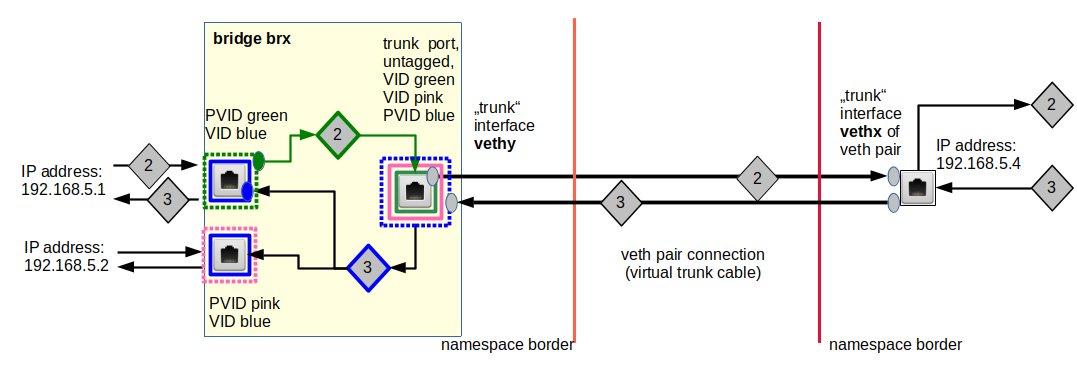
The following drawing illustrates some principles:
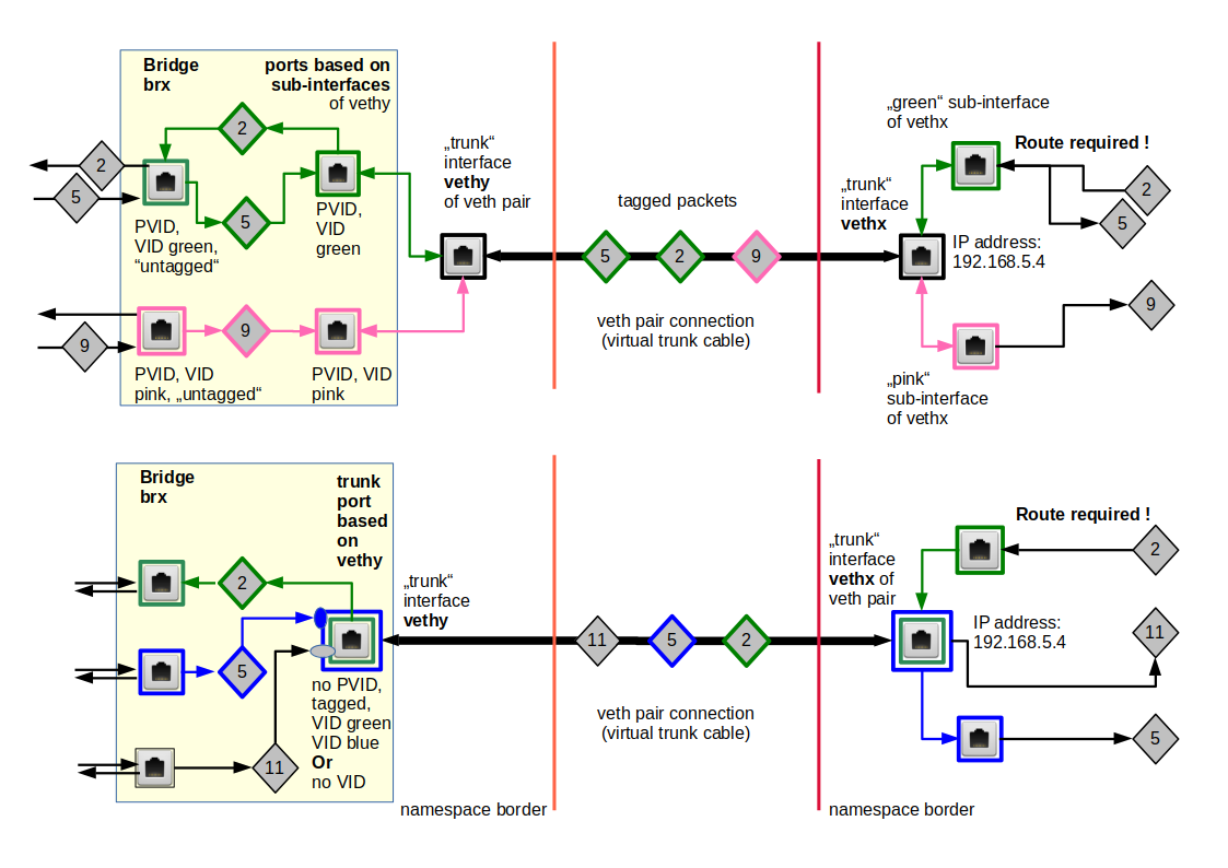
We have symbolized packets by diamonds. Different colors correspond to different tag numbers (VLAN IDs – VIDs, PVIDs).
In the scenario of the upper part the two standard access ports on the left side assign green or pink tags to untagged packets coming in from the outside of the bridge. This happens according to respective PVID values. The flag “untagged” ensures that packets leaving the ports to the bridge’s outside first get stripped of any tags. The device itself which sits at the port may change this.
The virtual cable of a veth device can transport Ethernet packets with different VLAN tags. However, packet processing at certain targets like a network namespace or a bridge requires a termination with a suitable Ethernet device, i.e. an interface which can handle the specific tag of packet. This termination device is:
- either a veth sub-interface located in a specific network namespace
- or veth sub-interface inside a bridge ( => this creates a bridge port, which requires at least a matching VID)
- or a veth trunk interface inside a Linux bridge (=> this creates a trunk bridge port, which may or may not require VIDs, but gets no PVID.)
Both variants can also be combined as shown in the lower part of the drawing: One interface ends in a bridge in one namespace, whereas the other interface is located in another namespace and splits up into sub-interfaces for different VLAN IDs.
Untagged packets may be handled by the standard trunk interfaces of a veth device.
Note: In the sketch below the blue packet “x” would never be available in the target namespace for further processing on higher network layers.
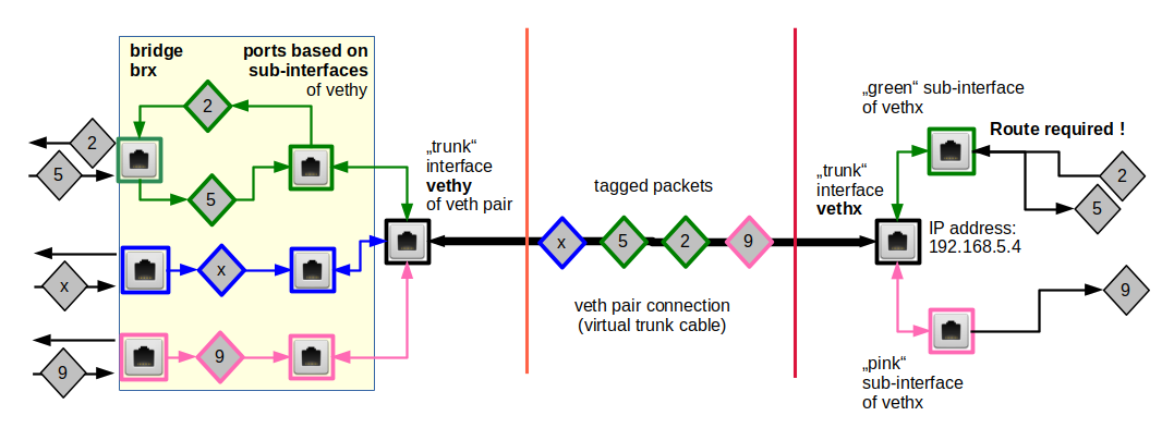
So, do not forget to terminate a trunk line with all required sub-interfaces in network namespaces!
A reasonably working setup of course requires measures and adequate settings on the bridge’s side, too. This is especially important for trunk interfaces at a bridge and trunk connection lines used to transport packets of various VLANs over a limited connection path to an external device. We come to back to relevant rules for tagging and filtering inside the bridge later on.
Below we call a veth interface port of a bridge which is based on the standard trunk interface a trunk port.
The importance of route definitions in network namespaces
Inside network namespaces where multiple VLANs terminate, we need properly defined routes for outgoing packets:
Situations where it is unclear through which sub-interface a packet shall be transported to certain target IP addresses, must always be avoided! A packet to a certain destination must be routed into an appropriate VLAN sub-interface! Note that defining such routes is not equivalent to enable routing in the sense of IP forwarding!
Forgetting routes in network namespaces with devices for different VLANs is a classical cause of defunct virtual network connections!
Note that one could avoid ambiguities and unclear conditions also
- by using multiple veth connections for different VLANs from a bridge to a namespace,
- by defining separate sub-nets containing NICs plus veth endpoints consistent with the VLANs.
You would use sub-net masks and respective IP-address ranges to achieve this. I will investigate a setup based on sub-nets and VLAN-aware bridges in another post series.
Commands to set up veth sub-interfaces for VLANs
Commands to define sub-interfaces of a veth interface and to associate a VLAN ID with each interface typically have the form:
ip link add link vethx name vethx.10 type vlan id 10
ip link add link vethx name vethx.20 type vlan id 20
ip link set vethx up
ip link set vethx.10 up
ip link set vethx.20 up
Sub-interfaces must be set into an active UP status! Inside and outside of bridges.
Setup of VLANs via a Linux bridge
Some years ago one could read articles and forum posts on the Internet in which the authors expressed their opinion that VLANs and bridging are different technologies which should be separated. I take a different point of view:
We regard a virtual bridge not as some additional tool which we somehow plant into an already existing VLAN landscape. Instead, we set up (virtual) VLANs by configuring a virtual Linux bridge.
A Linux bridge today can establish a common “heart” of multiple virtual VLANs – with closing and opening “valves” to separate the traffic of different circulation paths. From a bridge/switch that defines a VLAN we expect
- the ability to assign VLAN tags to Ethernet packets
- and the ability to filter packets at certain ports according to the packets’ VLAN tags and defined port/tag relations.
- and the ability to emit untagged packets at certain ports.
In many cases, when a bridge is at the core of simple separated VLANs, we do not need to tag outgoing packets to clients or network namespaces at all. All junction settings for the packets’ paths are defined inside the bridge!
Tagging, PVIDs and VIDs – VLAN rules at Linux bridge ports
What happens at a bridge port with respect to VLANs and packet tags? Almost the same as for real switches. An important point is:
We must distinguish the treatment of incoming packets from the handling of outgoing packets at one and the same port.
As far as I understand the present working of virtual Linux bridges, the relevant rules for tagging and filtering at bridge ports are the following:
- The bridge receives incoming packets at a port and identifies the address information for the packet’s destination (IP => MAC of a target). The bridge then forwards the packet to a suitable port (target port; or sometimes to all ports) for further transport to the destination.
- The bridge learns about the right target ports for certain destinations (having an IP- and a MAC-address) by analyzing the entry of ARP protocol packets (answer packets) into the bridge at certain ports.
- For setting up VLANs based on a Linux bridge we must explicitly activate “VLAN filtering” on the bridge (commands are given below).
- We can assign one or more VIDs to a bridge port. A VID (VLAN ID) is an integer number; the default value is 1. At a port with one or more VIDs both incoming tagged packets from the bride’s outside and outgoing tagged packets forwarded from the bridge’s inside are filtered with respect to their tag number and the port VID(s): Only, if the packet’s tag number is equal to one of the VIDs of the ports the packet is allowed to pass.
- Among the VIDs of a port we can choose exactly one to be a so called PVID (Port VLAN ID). The PVID number is used to handle and tag untagged incoming packets. The new tag is then used for filtering inside the bridge at target ports. A port with a PVID is also called “access port”.
- Handling of incoming tagged packets at a port based on a veth sub-interface:
If you attached a sub-interface (for a defined VLAN ID number) to a bridge and assigned a PVID to the resulting port then the tag of the incoming packets is removed and replaced by the PVID before forwarding happens inside the bridge. - Incoming packets at a standard trunk veth interface inside a bridge:
If you attached a standard (trunk) veth interface to a bridge (trunk interface => trunk port) and packets with different VLAN tags enter the bridge through this port, then only incoming packets with a tag fitting one of the port’s VIDs enter the bridge and are forwarded and later filtered again. - Untagged outgoing packets: Outgoing packets get their tag number removed, if we configure the bride port accordingly: We must mark its egress behavior with a flag “untagged” (via a command option; see below). If the standard veth trunk interface constitutes the port and we set the untagged-flag the packet leaves the bridge untagged.
- Retagging of outgoing untagged packets at ports based on veth sub-interfaces:
If a sub-interface of a veth constitutes the port, an outgoing packet gets tagged with VLAN ID associated with the sub-interface – even if we marked the port with the “untagged” flag. - Carry tags from the inside of a bridge to its outside:
Alternatively, we can configure ports for outgoing packets such that the packet’s tag, which the packet had inside the bridge, is left unchanged. The port must be configured with a flag “tagged” to achieve this. An outgoing packet leaves a trunk port with the tag it got/had inside the bridge. However, if a veth sub-interface constituted the port the tag of the outgoing packet must match the sub-interface’s VLAN ID to get transported at all. /li> - A port with multiple assigned VIDs and the flag “tagged” is called a “trunk” port. Packets with different tags can be carried along the outgoing virtual cable line. In case of a veth device interface the standard (trunk) interface and not a sub-interface must constitute such a port.
So, unfortunately the rules are many and complicated. We have to be especially careful regarding bridge-ports constituted by VLAN-related sub-devices of veth endpoints.
Note also that point 2 opens the door for attacking a bridge by flooding it with wrong IP/MAC information (ARP spoofing). Really separated VLANs make such attacks more difficult, if not impossible. But often you have hosts or namespaces which are part of two or more VLANs, or you may have routers somewhere which do not filter packet transport sufficiently. Then spoofing attack vectors are possible again – and you need packet filters/firewalls with appropriate rules to prevent such attacks.
Note rule 6 and the stripping of previous tags of incoming packets at a PVID access port based on a veth sub-interface! Some older bridge versions did not work like this. In my opinion this is, however, a very reasonable feature of a virtual bridge/switch:
Stripping tags of packets entering at ports based on veth sub-interfaces allows the bridge to overwrite any external and maybe forged tags. This helps to keep up the integrity of VLAN definitions just by internal bridge settings!
The last three points of our rule list are of major importance if you need to distinguish packets in terms of VLAN IDs outside the bridge! The rules mean that you can achieve a separation of the bridge’s outgoing traffic according to VLAN IDs with two different methods :
- Trunk interface connection to the bridge and sub-interfaces at the other side of an veth cable.
- Ports based on veth sub-interfaces at the bridge and veth sub-interfaces at the other side of the cable, too.
We discuss these alternatives some of our next experiments in more detail.
Illustration of packet transport and filtering
The following graphics illustrates packet transport and filtering inside a virtual Linux bridge with a few examples. Packets are symbolized by diamonds. VLAN tags are expressed by colors. PVIDs and VIDS at a port (see below) by dotted squares and normal squares, respectively. The blue circles have no special meaning; here some paths just cross.
The main purpose of this drawing is to visualize our bunch of rules at configured ports and not so much reasonable VLANs; the coming blog posts will discuss multiple simple examples of separated and also coupled VLANs. In the drawing only the left side displays two really separated VLANs. Ports A to D illustrate special rules for specially configured ports. Note that not all possible port configurations are covered by the graphics.
With the rules above you can now follow the paths of different packets through the drawing. This is simple for packet “5”. It gets a pink tag at its entry through the lowest port “D“. Its target is a host in th enetwork segment attached to port C. So, its target port chosen by the bridge is port “C” where it passes through due to the fact that the VID is matching. Packet “2” follows an analogous story along its journey through ports A and B.
All ports on the left (A, B, C, D) have gotten the flag “untagged” for outgoing packets. Therefore packets 5 and 2,6,7 leave the bridge untagged. Note that no pink packets are allowed to enter ports A and B. Vice versa, no green packets are allowed to leave target ports C and D. This is indicated by the filters.
Port “E” on the right side would be a typical example for a trunk port. Incoming and outgoing green, pink and blue packets keep their tags! Packet 8 and packet 9, which both are forwarded to their target port “E“, therefore, move out with their respective green and pink tags. The incoming green packet “7” is allowed to pass due to the green VID at this port.
Port “D“, however, is a strange guy: Here, the PVID (blue) differs from the only VID (green)! Packet “6” can enter the bridge and leave it via target port “B“, which has two VIDs. Note, however, that there is no way back! And the blue packet “3” entering the bridge via trunk port “E” for target port “D” is not allowed to leave the bridge there. Shit happens …
The example of port “D” illustrates that VLAN settings can look different for outgoing and incoming packets at one and the same port. Still, also ports like “D” can be used for reasonable configurations – if applied in a certain way (see coming blog posts).
Commands to set up the VLANs via port configuration of virtual Linux bridges
We first need to make the bridge “VLAN aware“. This is done by explicitly activating VLAN filtering. On a normal system (in the root namespaces) and for a bridge “brx” we could enter
echo 1 > /sys/class/net/brx/bridge/vlan_filtering
But in artificially constructed network namespaces we will not find such a file. Therefore, we have to use a variant of the “ip” command:
ip link set brx type bridge vlan_filtering 1
For adding/removing a VID or PVID to/from a bridge port – more precisely a device interface for which the bridge is a master – we use the “bridge vlan” command. E.g., in the network namespace where the bridge is defined and has a veth-related sub-device as a port the following commands could be used:
bridge vlan add vid 10 pvid untagged dev veth53
bridge vlan add vid 20 untagged dev veth53
bridge vlan del vid 1 dev veth53
See the man page for more details!
Note: We can only choose exactly one VID to be used as a PVID.
As already explained above, the “untagged” option means that we want outgoing packets to leave the port untagged (on egress).
Data transfer between VLANs?
Sometimes you may need to allow for certain clients in one VLAN (with ID x) to access specific services of a server in another VLAN (with ID y). Note that for network traffic to cross VLAN borders you must use routing in the sense of IP forwarding, e.g. in a special network namespace that has connections to both VLANs. In addition you must apply firewall rules to limit the packet exchange to exactly the services you want to allow and eliminate general traffic.
There is one noteworthy and interesting exception:
With the rules above and a suitable PVID, VID setting you can isolate and control traffic by a VLAN from a sender in the direction of certain receivers, but you can allow answering packets to reach several VLANs if the answering sender (i.e. the former receiver) has connections to multiple VLANs – e.g. via a line which transports untagged packets (see below). Again: VLAN regulations can be different for outgoing and incoming packets at a port!
An example is illustrated below:
Intentionally or by accident – the bridge will do what you ask her to do at a port in IN and OUT directions. Packet “2” would never enter and leave the lower port.
However, a setup as in the graphic breaks total isolation, nevertheless! So, regarding security this may be harmful. On the other side it allows for some interesting possibilities with respect to broadcast messages – as with ARP. We shall explore this in some of the coming posts.
Note that we always can involve firewall rules to allow or disallow packet travel across a certain OUT port according to the IP destination addresses expected behind a port!
The importance of a working ARP communication
Broadcast packets are not allowed to leave a VLAN, if no router bridges the VLANs. The ARP protocol requires that broadcast messages from a sender, who wants to know the MAC address of an IP destination, reach their target. For this to work your VID and PVID settings must allow the returning answer to reach the original sender of the broadcast. Among other things this requires special settings at trunk ports which send untagged packets from different VLANs to a target and receive untagged packets from this target. Without a working ARP communication on higher network protocol layers to and from a member of a VLAN to other members will fail!
VLANs in one and the same sub-net?
So far, we have discussed packet transport by considering packet tags and potentially blocking VID rules of devices and bridge ports. We have not talked about IP-addresses and net-segregation on this level. So, what about sub-net definitions?
This is a critical aspect the reader should think a bit about when following the discussions of concrete examples in the forthcoming posts. In most of the cases the VLAN definitions for bridge ports will separate traffic between external systems/devices with IP-addresses belonging to one and the same sub-network!
Thus: VLANs offer segregation beyond the level of sub-networks.
However, strange situations may occur when you place multiple tag-aware devices – as e.g. sub-devices (for different VIDs) of a veth-endpoint – into a network namespace (without a bridge). How to choose the right channel (veth-sub-device) then automatically for packets which are send to the outside of the namespace? And what about broadcasts required e.g. by ARP to work?
Conclusion
Veth devices and virtual Linux bridges support VLANs, VLAN IDs and a tagging of Ethernet packets. Tagging at pure veth interfaces outside a bridge requires the definition of sub-interfaces with associated VLAN IDs. The cable between a veth interface pair can be seen as a trunk cable; it can transport packets with different VLAN tags.
A virtual Linux bridge can become the master of standard interfaces and/or sub-interfaces of veth devices – resulting in different port rules with respect to VLAN tagging. Similar to real switches we can assign VIDs and PVIDs to the ports of a Linux bridge. VIDs allow for filtering and thus VIDs are essential for VLAN definitions via a bridge. PVIDs allow for a tagging of incoming untagged packets or a retagging of packets entering through a port based on veth sub-interfaces. We can also define whether packets shall leave a port outwards of the bridge untagged or tagged.
Separated VLANs can, therefore, be set up with pure settings for ports inside a bridge without necessarily requiring any package tagging outside.
We now have a toolset for building reasonable VLANs with the help of one or more virtual bridges. In the next blog post
Fun with veth-devices, Linux bridges and VLANs in unnamed Linux network namespaces – V
we shall apply what we have learned for the setup of two separated VLANs in an experimental network namespace environment.